TM 11-6625-622-40
S5, terminal 2 and jack J19, pin b. Jack J11 on
the test unit is used instead of PHONE jack J1
of the receiver-transmitter. A 300-ohm load may
be placed in the audio output circuitry of the
receiver-transmitter by switch S5.
c. Key Line Circuit. The key line circuit which
is u s e d for remote keying of the receiver-
transmitter passes through the test unit as fol-
lows: From jack J12, terminal 2, to switch S6
terminal 3. If S6 is at 714E2/3, connection is
made to S6 terminal 2 which is connected to ANT.
CPLR jack J6 pins N, P, and R, 516H1, con-
nector J5 pin 1, and to the receiver-transmitter,
through 618T2/3 connector J1 pin 55. Connec-
tion is also made from jack J12 terminal 2 to
jack J19 pin m. If switch S5 of the control unit
is at AM, USB, or LSB, the key line is returned
through jack J19 pin q to switch S6 terminal 1.
When S6 is at 714E2/3, connection is again
made to terminal 2 of S6, completing the key
line circuit. KEY switch S9 is connected to jack
NOTES:
J12 terminal 2 and places a ground on the key
line circuit in either the up or down position.
1.
INDICATES EQUIPMENT MARKINGS.
2. UNLESS OTHERWISE INDICATED ALL RESISTANCE
VALUES ARE IN OHMS, ALL CAPACITANCE VALUES
2-7. TUNE POWER Switch
ARE IN UUF.
TM6625-622-45-11
TUNE POWER switch S4 connects to J1 pin 10
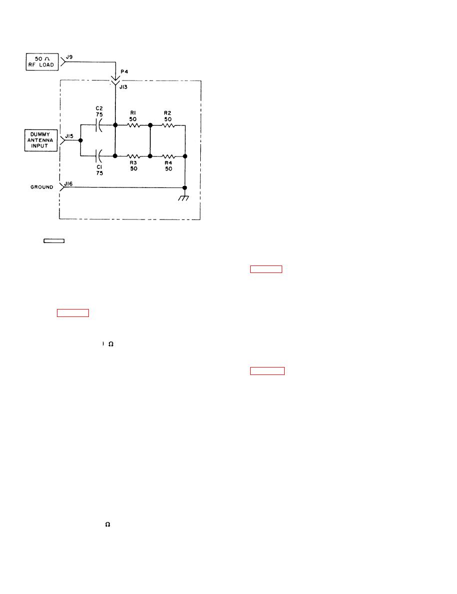
Figure 2-1. Dummy antenna, schematic diagram.
and, when depressed, grounds the receiver-trans-
m i t t e r tune powerline to check the functioning
2-6. Audio Circuits
of the tune circuitry within the receiver-trans-
m i t t e r . Switch S4 is not used with antenna
couplers. To avoid damage to the receiver-trans-
a. Audio Inputs to Receiver-Transmitter. A
mitter, it should not be depressed for more than
balanced audio input is supplied to the receiver-
15 seconds.
t r a n s m i t t e r from 600
BAL AUDIO IN jack
J8. The audio goes from jack J8, through 618T2/3
28. Control, Radio Set C3940/ARC94
connector J1 pins 53 and 37, to the AM/audio
amplifier module of the receiver-transmitter. An
unbalanced audio input is supplied to the receiver-
The radio set control (mounted on the front
transmitter from MIKE jack J12. The audio goes
panel of the test unit) is connected to the test
from terminal 1 of J12, through 618T2/3 connec-
unit through jack J19. The l-MHz control, SIA,
tor J1 pin 54, to the AM/audio amplifier module
selects a portion of the receiver-transmitter op-
of the receiver-transmitter. MIKE jack J12 on the
erating frequency in l-MHz steps. The 1-MHz
test unit can be used instead of MIC jack J2
control is connected to the receiver-transmitter
of the receiver-transmitter.
by way of pins A through E of jack J19, and
pins 32 through 36 of 618 T2/3 connector J1.
b. Audio Outputs from Receiver-Transmitter.
The 0.1-MHZ control, S2, selects a portion of
The audio output of the receiver-transmitter may
the receiver-transmitter operating frequency in
be monitored at HEADSET jack J11. The audio
0.1-MHZ steps. The 0.1-MHZ control is connected
is supplied through connector J1, pins 57 and 58.
to the receiver-transmitter by way of pins K
From connector J1 pin 58, audio goes to jack
through N of jack J19, and pins 45 through 48
J19 pin a, which is jumpered to jack J19 pin c
through the control unit. Pin c of jack J19 is
of connector J1. The 0.01-MHZ control, S3, se-
lects a portion of the receiver-transmitter operat-
connected to jack J11 terminal 1. From pin 57
ing frequency in 0.01-MHZ steps. The 0.01-MHZ
of connector J1, the audio is connected to jack
J 1 1 , terminal 2,300
AUDIO LOAD switch
control is connected to the receiver-transmitter
2-2

