
TM 11-6625-441-34
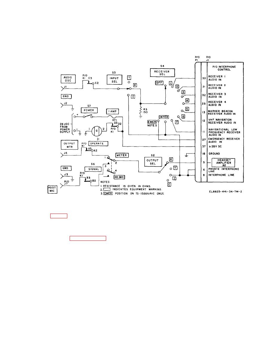
Figure 2-2. Interphone test set, receiving test circuit, simplified schematic diagram.
2-3. Transmission Test Circuit Functioning
i n t e r p h o n e control. H o w e v e r , transmission
cannot be accomplished until KEYING switch S1
NOTE
is placed in either the RADIO or INTER position.
Application o f 28-volt dc power to
When switch S1 is in the RADIO position, a
energize the interphone control is
ground is made to the transmitter control cir-
described in paragraph 2-2a.
cuitry of the interphone control through terminal
Transmitting test circuitry of the interphone test
15 of J1. When switch S1 is in the INTER
set tests the transmitter output and control
position, interphone relay K1 of the interphone
circuits of the interphone control.
control is energized completing the interphone
a. The audio input signal to the interphone
transmitting circuits of the interphone control.
control is provided by either the audio oscillator
b. The transmitter audio output signal from
or the microphone. Microphone audio input
the interphone control is applied direct to S5B of
signals are applied direct to terminal 3 of J 1
TRANSMITTER SEL switch S5, and to contact
through contacts 6 and 5 of SIGNAL switch S6
T of OUTPUT SEL switch S2. When switch S2 is
when held in the HD MIC position. The audio os-
in the T position, and switch S6 is in the METER
position, the audio output signal is applied to the
cillator input signal is applied to INPUT SEL
switch S3 through contacts C2 and C3 of relay
output meter. When switch S2 is in the T position
K1. When switch S3 is in the T position the audio
and switch S6 is in the HD MIC position, the
oscillator input signal is applied to load resistors
audio output signal is routed to HDST MIC jack
R1 and R2. The audio signal developed across R1
J7 and into the headset. When testing the audio
is applied through contacts 4 and S of SIGNAL
output signal sidetone from the interphone
control, switch S2 is in R and switch S4 is in
switch S6 (in METER position) to terminal 3 of
INTER. When switch S1 is placed and held in
J1, and into microphone preamplifier A3 of the
2-3
