Page 14, paragraph 19: In last line, change "475"
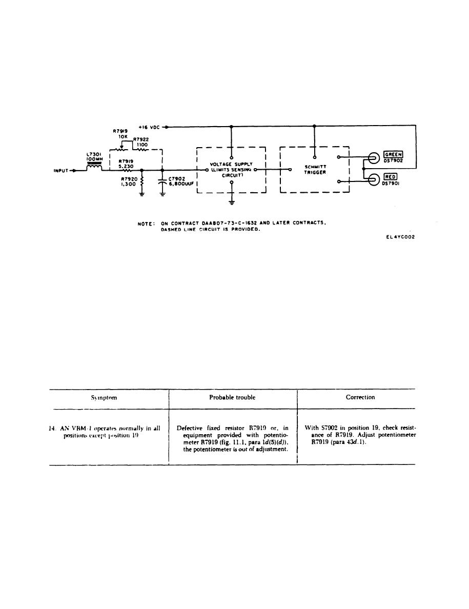
In some equipment (para 1d(5)(d)), the tested
to 402.
voltage is connected through rf choke L7301 and
Paragraph 22: In line 5, add "R7918" after
across voltage divider network consisting of
-
variable resistor R7919 and resistors R7922 and
C7901.
R7920.
Paragraph 23, line 5. "R7901" is changed to
Figure 10.1 is superseded by new figure 10.1.
read R7910.
Page 16, paragraph 27.1. The following sentence
is added after the second sentence:
Figure 10.1. Test in selector switch position 19. simplified
schematic diagram.
Page 29, paragraph 33d. Troulbleshooting Chart.
Page 20, paragraph 33d, Troubleshooting Chart,
Make the following changes for symptom 2; insert
Make the following changes for symptom 4; insert
the material before the first probable trouble and
the material before the first probable trouble and
correction ("Defective R7902, etc."). In Probable
correction ("Diode CR7902, etc."). In Probable
trouble column, insert: Knob on selector switch S7901 is set
trouble column. insert: In equipment provided with poten-
180 degrees from proper position.
tiometer R7902 (fig. 11.1. para Id(5)(d)). the potentiometer is out
of adjustment.
In Correction column, insert: Set S7901 to position 11. If
In Correction column, insert: Adjust potentiometer
GREEN Indicator lights. remove the switch knob and install it
R7902 (para 43d.1).
with the arrow pointing to position A. If GREEN indicator does
Page 21. paragraph 33d, Troubleshooting Chart.
not Iight, replace the lamp.
Add the following material after symptom 13.
4

