
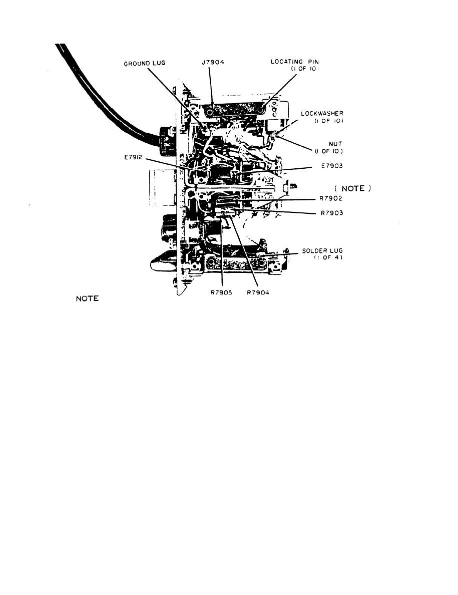
R7902 IS R7923 (1100 OHMS ) WHEN POTENTICMETERS R7902 AND R7919
PROVIDED ON CONTRACT DAAB05 -73 6 - 1632 (1973) AND
ARE
SUCEEDING CONTRACTS.
EL4YC004
Figure 15. Test Set, Radio TS-1777/VRM-1 and TS-1777A/VRM-1
front panel chassis, top view.
indicator lights. The output of the 721A should be
Page 35, paragraph 43. The following is added
between 19.00 and 21.10 volts dc.
after subparagraph d:
(5) If necessary, adjust potentiometer R7902
d.1. DC Circuits (Positions 2 and 19). The
to assure the condition in (4) above.
following procedures are performed on those
(6) Reduce the 721A output to 0 volt dc.
equipments with potentiometer R7902 on position 2
(7) Turn the TS-1777A/VRM-1 selector switch
of switch R7910 and potentiometer R7919 on posi-
to position 19.
tion 19 of the switch (fig. 15 and 39.2).
(8) Set potentiometer R7919 (fig. 11.2 and 15)
approximately midrange.
(1) Reduce the 721A output to 0 volt dc. Use
(9) Raise the 721A output until the GREEN
the TS-443/U to measure the 721A output.
indicator lights. The output of the 721A should be
(2) Turn the TS-1777A/VRM-1 selector to
between 13.00 and 14.70 volts dc.
position 2.
(10) If necessary, adjust potentiometer R7919
(3) Set potentiometer R7902 (fig. 11.2 and 15)
to assure the condition in (9) above.
approximately midrange.
Make the following changes as idicated:
(4) Raise the 721A output until the GREEN
8
