
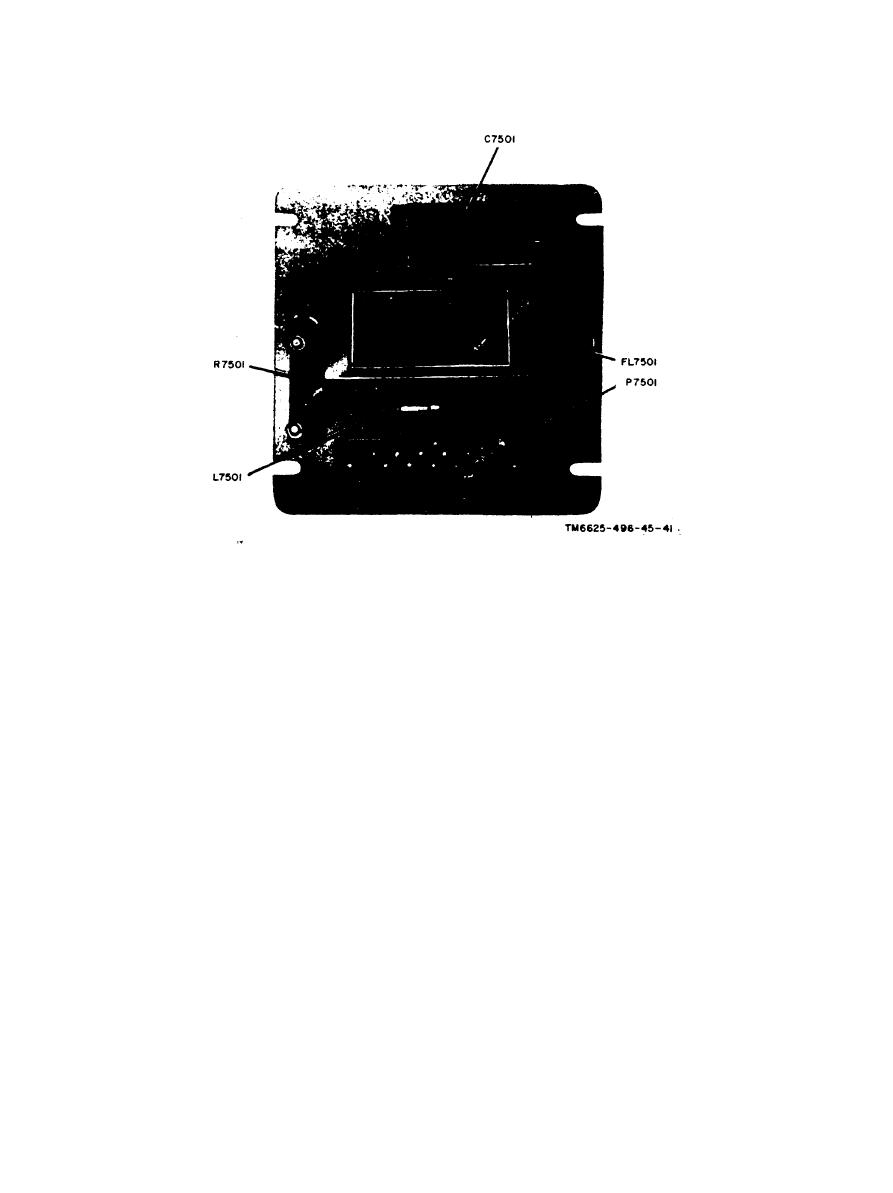
F i g u r e 30. Assembly A 7600, parts location
10 mv. A normal indication should
maximum indication on the
ME-26B/U and record the indica-
be +1.0 volts dc 0.30.
(4) Adjust the 606 A frequency to 13.000
tion.
mc while maintaining a 411A in-
(4) Increase the 606A output to 20 mv
as indicated on the 411A. Record
dication of 10 mv. A normal indi-
cation should be +1.0 volts dc 0.30.
the ME-26B/U indication.
(5) A normal indication, noted in (3)
(5) If the indications obtained in (3) and
a b o v e , should be +4.0 volts dc
(4) above are normal, trouble iso-
lation in assembly A7600 is com-
(6) A normal indication, noted in (4)
plete.
above, should be + 5.5 volts dc mini-
(6) If indications obtained in (3) and
mum.
( 4 ) above are low, proceed to d
(7) If the indications obtained are low
below.
d. Isolation.
or absent, proceed to d below.
c. Bandwidth Test.
(1) Adjust the 606A for a frequency of
11.500 mc at a level of 4.9 mv as
(1) Adjust the 606A for a 411A indi-
indicated on the 411A.
cation of 10 mv.
(2) Measure the listed typical signal
(2) Adjust potentiometer R7611 for an
and dc voltage in the Chart below
ME-26B/U indication of +3 volts
to isolate the faulty part. Measure
dc.
the ac voltages with an ME-30B/U;
(3) Adjust the 606A output frequency to
m e a s u r e the dc voltage with an
10.500 mc and adjust the output
level to maintain a 411A indication
ME-26B/U.
59
