TM 11-6625-828-12
CHAPTER 3
OPERATING INSTRUCTIONS
Control or indicator
Function
3-1. Test Set, Radio AN/ARM-5A Operator's Controls
150~
20 percent when adjusted
and Indicators
to 20 on the upper scale
of the % M meter.
Control or indicator
Function
30~ 30 percent when adjusted
POWER-STAND BY
In the POWER position, turns on
to 30 on the upper scale
switch.
SG-66B/ARM-5.
of the % M meter.
In the STAND BY position, turns off
9960~ 30 percent when adjusted
SG-66B/ARM-5 and turns on
to 30 on the upper scale
internal heaters.
of the % M meter.
Indicator lamp (red) ------- Lights when power is applied to
OMNI 30 percent of 30 ~ and 30
SG-66B/ARM-5.
percent of 9960 ~.
MC switch ------------------- Selects desired crystal frequency
EXT Percentage of modulation
as follows:
may be read directly
Position
Crystal
from the lower scale of
A
Y101 (110.9 mc nom)
the % M meter.
B
Y102 (114.9 mc nom)
1000~ Percentage of modulation
RF LEVEL SET
Adjusts RF level to LEVEL SET
is adjustable from 0 to
control.
line on RF meter.
100 percent as read on
000 ~ MOD control -------- Adjusts percentage of 1,000 cps
% M meter.
modulation level as indicated
90 ~ MOD control
Adjusts percentage of 90-cps
on % M meter.
modulation level as indicated on
51-ohm termination ------- Provides a 51-ohm resistive load
the C7 M meter.
across the RF OUTPUT 1
150~ MOD control
Adjusts percentage of 150-cps
VOLT connector.
modulation level as indicated on
ATTENUATOR uv
Adjusts RF output from 1 to
the % M meter.
control. 10,000 microvolts.
30~ MOD control
Adjusts percentage of 30-cps
IDENTIFIER
In ON position, applies a 1000 -
modulation level as indicated on
switch.
audio tone, keyed at approxi-
the % M meter.
mately 4 cps, to omni and
9960~ MOD control
Adjusts percentage of 9960-cps
amplitude localizer signals.
modulation level as indicated on
MODULATION
Selects type of modulation to be
the % M meter.
switch.
applied to carrier signal as
OMNI TRACK switch.
Selects the desired track setting in
follows:
degrees
for
testing
omni
Position
Modulation
equipment.
Position
Modulation
% M meter
Indicates percentage of modulation
90 ~
20 percent when ad-
level applied to carrier.
justed to 20 on
ZERO SET controls
Permits calibration and adjustment
the upper scale of
of both the % M and the RF
% M meter.
meter circuits.
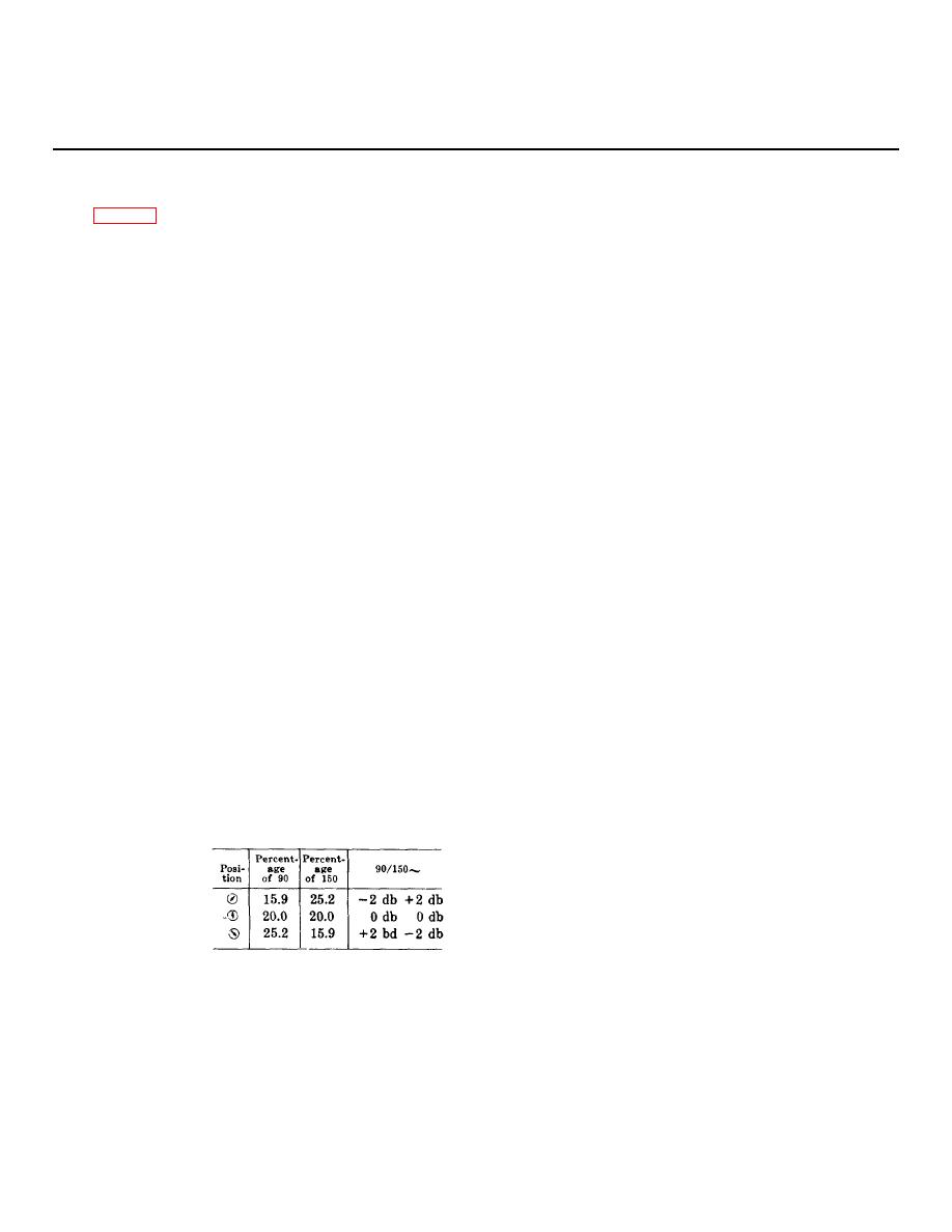
AMP LOC Applies modulation of
RF meter
Indicates level of RF outputs.
90/150 cps as fol-
lows:
3-1


