TM 11 5895-1096-40
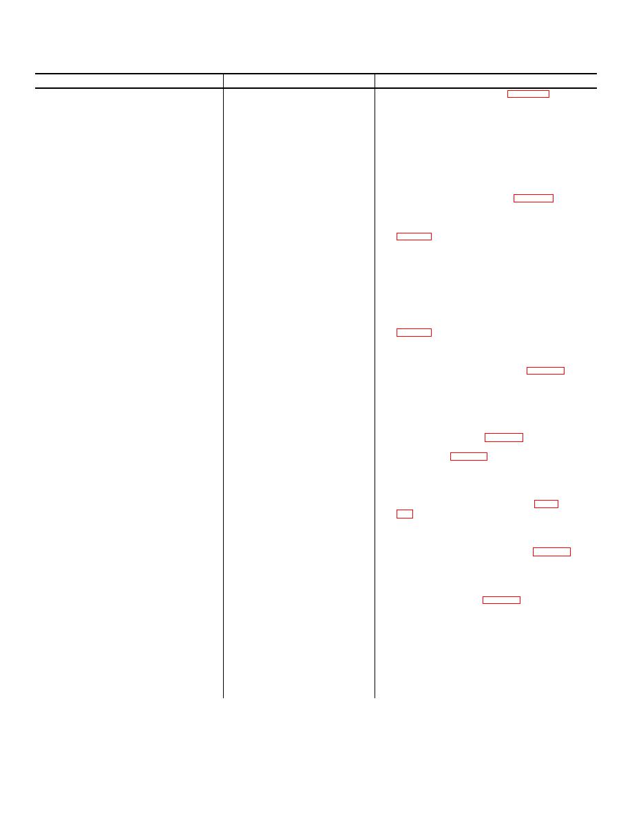
Table 3-6. Encode Generator Circuit Card Troubleshooting
Malfunction
Probable Cause
Corrective Action
1. No CODE OUT or SYNC OUT signals generated.
a. Defective DC supply components
a. Set up test equipment as shown in figure 3-6 Using
CR3, CR4, C14.
Multimeter N/USM-223, check for + 18 VDC nomi-
nal at + side of C14.
(1) If CORRECT, go to b below.
(2) If INCORRECT, disconnect test set from 120
VAC source. Using Multimeter AN/USM-223,
check CR3, CR4, C14 and replace defective
component.
b. Defective DC supply components
b. Disconnect test set from 120 VAC source.
CR2, C12, C13, R20.
Using Multimeter AN/USM-223 check CR2, C12,
C13, R20. Replace defective component.
2. Erratic of no CODE OUT signal generated.
a. Defective clock component.
a. Set up test equipment as shown in figure 3-6. Using
SYNC OUR normal.
Oscilloscope OS-262P/U, connect CHI probe to
TP4. Adjust horizontal, vertical position, and trig-
ger level as required to observe display as shown in
figure 3-2 (i).
NOTE
Only upper trace will be displayed on
oscilloscope.
(1) If CORRECT, go to b below.
(2) If INCORRECT, check Ul, U2, Yl and asso-
ciated components. Replace defective
component.
b. Defective divider U5B.
b. Using Oscilloscope OS-262P/U, connect CH2
probe to TP2 and observe display as shown in
figure 3-2 (i).
(1) If CORRECT, go to c below.
(2) In INCORRECT, replace U5.
c. Defective divider U5A:
c. Using Oscillscope OS-262P/U, connect CH2 probe
to TPI and observe display as shown in figure 3-2 (j).
(1) If CORRECT, go to d below.
(2) If INCORRECT replace U5.
d. Defective reset line component.
d. Using Oscilloscope OS-262P/U, connect CH2
probe to TP3 and connect CHI probe to PI-20
(SYNC). Set test set MODULATION to MANUAL
and adjust oscilloscope controls as required to ob-
serve display as shown in figure 3-2 (k). Set
test set MODULATION to CONTINOUS and ob-
serve display in figure 3-2 (1).
(1) If CORRECT, go to e below.
(2) If INCORRECT, check CRI, C8, RI5, R16, U6.
Replace defective component.
e. Defective code output component
e. Using Oscilloscope OS-262P/U, connect CH2 probe
U7A, U7B.
to PI-15 and observe display as shown in figure
3-2 (m).
(1) If CORRECT, go to f below.
(2) If INCORRECT, replace U7.
f. Defective code output component
f. Using Oscilloscope OS-262P/U, connect CH2 probe
U 1.
to Pl-17 and observe display as shown in figure 3-2
(o). Replace UI.
3. Erratic or no SYNC OUT signal generated.
Defective sync component.
Using Oscilloscope OS-262P/U, connect CHI probe
CODE OUT normal.
to TP4, CH2 probe to U3-13. Adjust horizontal,
vertical position, and trigger level as required to ob-
serve display as shown in figure 3-2 (p)
(1) if INCORRECT, replace U3.
(2) if CORRECT, check R13, Q2. Replace defective
component.
4. Signal not present at 19.25 MHz OUT connector J4
a. Defective probe power supply.
a. Using Multimeter AN/USM-223, check LI, L2,
when using external probe amplifier assembly.
R18, R19, Q3, Q4. Replace defective component.
b. Defective DC blocking capacitor
b. Replace C9.
C9.
3-14


