
TM 11 5895-1096-40
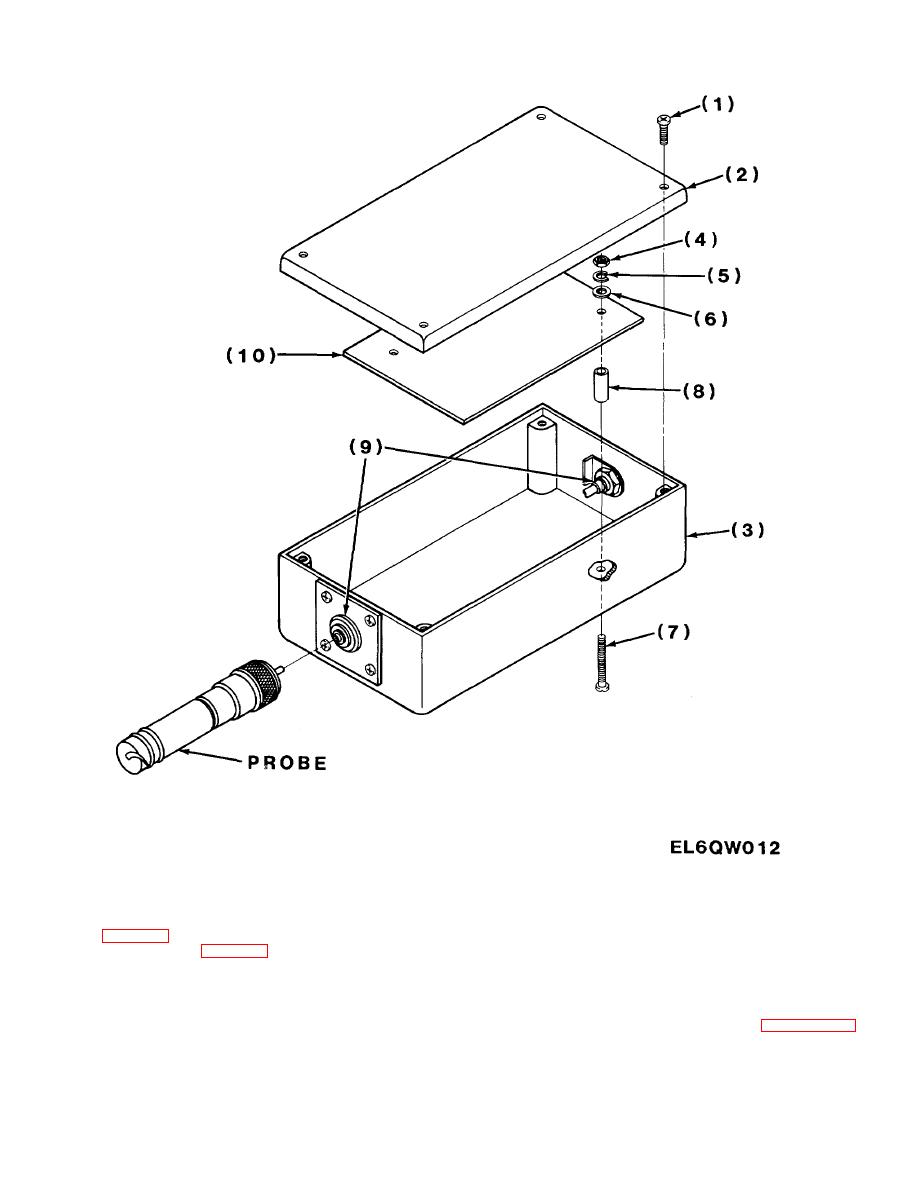
Figure 3-9. Exploded View of Probe Amplifier.
(6)
Remove defective switch (6) from panel (7).
3-17. Parts Replacement
(7)
Install new switch (6) into panel.
a. Code Selector Switch S1, S2, S3 Replacement.
(8)
Install nut with washer (5), and tighten.
Refer to figure 3-8 and replace the defective switch as follows:
(9)
Install bushing (4), coil spring (3), and knob on
(1) Disassemble test set (para 3-16).
new switch.
(2) Tag and unsolder all wires connected to defective switch.
(10)
Install knob setscrew (1), and tighten.
(3) Remove knob setscrew (1).
(11)
Solder all wires in their correct position on
(4) Remove knob (2), coil spring (3), and bushing (4).
switch.
(5) Remove nut with washer (5).
(12)
Reassemble
test
set
3-19
