
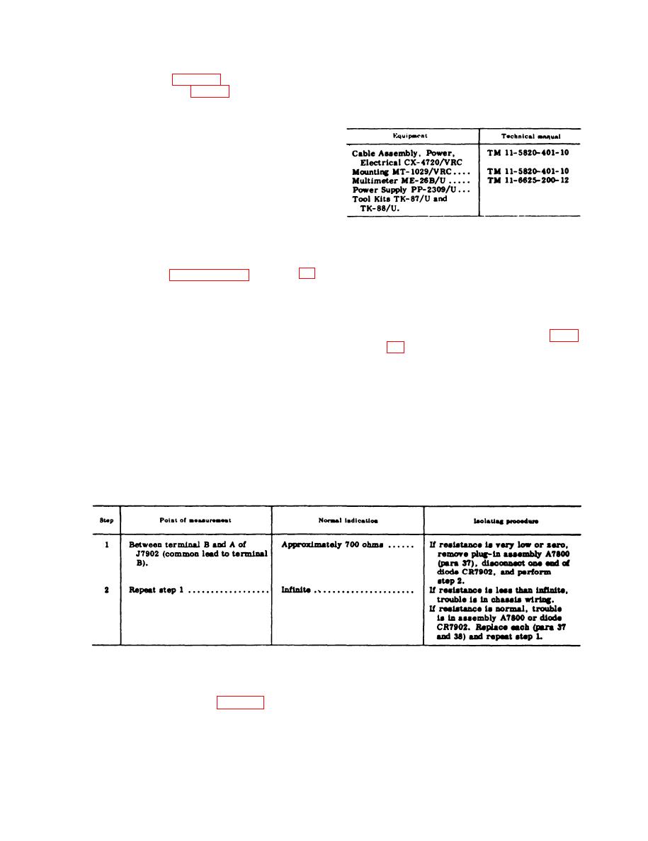
30. Test Equipment Required
diagram (fig. 39) to find normal
The following chart lists equipment re-
readings, and compare them with
quired for troubleshooting Test Set, Radio
readings taken.
AN/VRM-1:
(2) Intermittent troubles. In all these
tests, the possibility of intermittent
troubles should not be overlooked.
If present, this type of trouble often
may be made to appear by tapping
or jarring the equipment. Check the
wiring and the connections to the
AN/VRM-l.
Section Il. TROUBLESHOOTING
Caution: Do not attempt removal or replacement of parts before reading the instruc-
tions given in paragraphs 35 through 40.
(4) Check to be sure that fuse F7901
31. Checking Dc Supply Circuit for Shorts
is good.
-
a. When to Check. Check for short cir-
(5) Remove the front panel and chas-
cuits and clear the trouble whenever ab-
sis assembly from the case (para
normal symptoms reported from opera-
tional tests indicate possible dc supply
c. Measurements. Make the resistance
circuit troub1es. (Refer to equipment
measurements indicated in the chart be-
performance checklist, TM 11-6625-496-
low. If abnormal results are obtained,
12.)
make the additional isolating checks out-
b. Conditions for Test. To prepare for
lined. When the faulty part is found, repair
the short-circuit tests, perform the fol-
the trouble before applying power to the
lowing operations:
unit.
(1) Turn the selector switch to A.
(2) Set the ON-OFF switch to ON.
age is applied to the OHMS lead of the ME-26BAJ.
(3) Disconnect CX-7899/VRM-l from
If another type of meter is used, determine the
the front panel of the TS-1777/
polarity of the ohmmeter leads before checking the
VRM-1.
dc supply circuit for shorts.
32. Test Setup
a. Power Supply Connections. For bench
-
testing power apply PP-2309/U is used
Remove the front panel and chassis as-
in place of a vehicular electrical system
semblies from the case (para 36) and make
which is normally used to furnish power
the test setup outlined below.
18
