
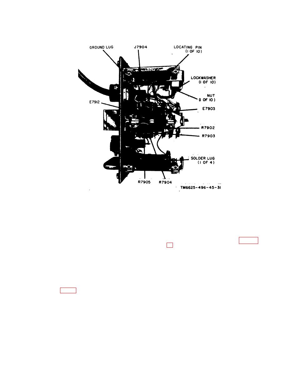
Figure 15. Test Set, Radio TS-1777/VRM-1 front panel chassis, top v i e w .
x. Replacement of Resistors Mounted on
case face so that the holes in the gasket
switch S7902.
line up with the holes in the case.
(1) Cut the resistor leads to the proper
length and make a good mechanical
40. Repair of Cables
connection at the solder lugs of
switch S7902.
and 19).
(2) solder the resistor 1 e a d to the
(1) Remove the outer cable shield con-
solder lugs of switch S7902. Be
nection from terminal E7903.
careful not to damage or drop
solder into the contacts of switch
(2) Remove the inner cab1e shield
S7902.
connection at the ground lug on
connectcr J7904.
39. Removal and Replacement of Case
(3) Remove the inner cable conductor
Gasket
connection at terminal E7912.
(4) Remove the coupling nut on the
a. Removal. Remove the gasket by peel-
front panel front side of the probe
ing it off the case face.
cable box connector, and remove
b. Replacement. Apply sealant to the
the cable, nut, washer, and grom-
replacement gasket and apply it to the
met.
29
