
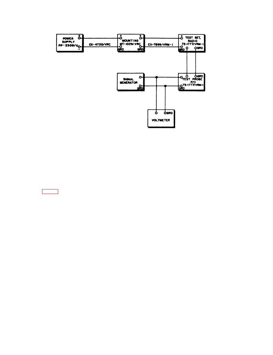
Figure 34. Test Set, Radio AN/VRM-1, final tests, block diagram.
(2) Adjust Hf Signal Generator 606A
411A. The RED indicator should be
lighted.
output frequency to 47.0 mc and
connect it to the test probe.
Increase the rf output of the 606A
(3) C o n n e c t Rf Millivoltmeter 411A
to 0.014 volt. The GREEN indicator
across the 606A output.
should be lighted
--
b. Position 18 Test.
67. Amplifier Test, 47.0-Mc
(1) Turn the selector switch to 18.
(2) Adjust the 606A for an output of
0 . 1 0 volt ac as indicated on the
check the ability of the TS-1777/VRM-l
41lA. The RED indicator should be
t o test the 47.0-mc amplifier circuit as
lighted.
directed below.
(3) Increase the rf output of the 606A
a. Preparation.
to 0.21 volt. The GREEN indicator
(1) Insert the test probe tip in test jack
should be lighted.
A, turn the selector switch to A,
and check to be sure that the
GREEN indicator lights.
68
