TM 11-6625-820-45
the phase shifting mode is needed (switch
position A).
a. BRGOBS switch S2 determines which
phase shifting circuit is used. When switch S2
is in the OBS position, the OBS resolver is
used to produce the desired phase shift. The
OBS indicator is the same type as used in an
aircraft installation. The 30-cycle reference sig-
nal is applied to the rotor of the resolver in
the OBS indicator. When the rotor is turned,
the phase of the signal at stator output is shift-
ed. A compass card is attached to the rotor, pro-
viding an indication of the number of degrees
of phase shift. This voltage is routed to the
radio receiver. For more information on the
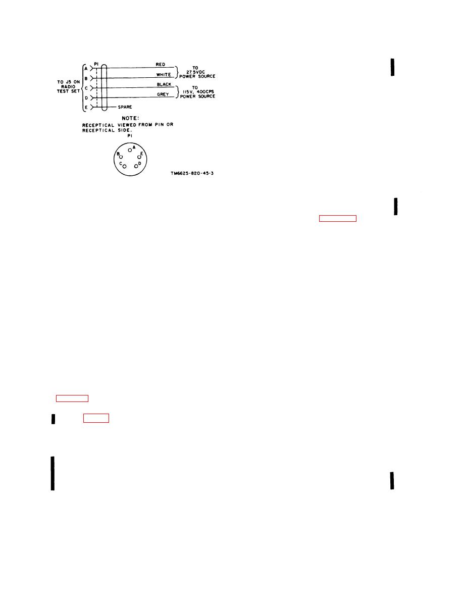
Figure 12. Cable Assembly, Power, Electrical
OBS indicator, refer to TM 11-5826-226-35
CX-11568/ARM-92, schematic diagram.
for Radio Receiving Sets AN/ARN-82 and
AN/ARN-82A. A schematic diagram of the
OBS indicator is shown in figure 1-3.
cuits is completed for the 115 volts, 400 cps
b. A resolver has the same electrical charac-
from pin D of J5 through fuse F3 to trans-
teristics as a transformer. Therefore, a trans-
former T1. Transformer T1 steps down the 115
former can be used to simulate a resolver. When
(volts, 400 cps to 26 volts, 400 cps. The 26
switch S2 is in the BRG position, precision
volts, 400 cps is routed to RMI connector P4,
bearing transformer T2 and its switching cir-
the compass simulator connector P1, and to con-
cuits are used to produce the desired phase
nector P3 of the radio receiver. The RMI ser-
shift. The 30cycle reference signal from the
voamplifier input is supplied with 26 volts, 400
radio receiver is applied through switch S2 to
cps from transformer T1 through resistors R6
the primary of transformer T2. This primary
and R7.
winding and resistor R3 simulate the rotor of a
b. From tie point 18 of TB1, the 27.5 volts
resolver. The phase shift through the second-
dc is routed to connector P2 of the radio re-
ary winding of the transformer must be the
ceiver, and also through fuse F2 to connector
same as the phase shift in the stator windings
of the resolver. This phase shift through trans-
J4 of the glide-slope receiver.
former T2 is adjusted to 83 at a dial setting
c. Tuning information from the control unit
of 300 by the loading on the tertiary wind-
is routed to TB1, and branches off to both con-
ing. The design of the transformer is such that
nectors P2 and J4, For further information on
the phase shift it produces is stable with var-
the control unit, refer to TM 115826-226-35
iations in alternating current (ac) or direct
f o r Radio Receiving Set AN/ARN-82. A
schematic diagram of the control unit is in fig-
current through the primary winding. The com-
bination of the precisely tapped secondary
windings of transformer T2 and the switching
1-4. Phase Shifting Circuits
arrangement (S3) produces the various voltage
ratios that correspond to the stator output of a
In the test set the two circuits that shift the
standard resolver. Each clockwise position of
phase of the 30-cycle reference signal are the
switch S3 simulates a clockwise rotation of a
O B S resolver and precision bearing trans-
resolver rotor in precise 30 increments. With
former T2.
T h e i r operation is described
switch S2 in the BRG position, the output volt-
In Test Set, Radio TS-2500A/ARM-
below.
a g e path from transformer T2 is through
92, RECEIVER MODEL switch S5 disables
switch S3, through switch S5 in Test Set,
p r e c i s i o n bearing transformer T3 and ad-
Radio TS-2500A/ARM-92, through switch S2,
justs the circuit of transformer T2 whenever
1 - 4 Change 2

