TM 11-6625-820-45
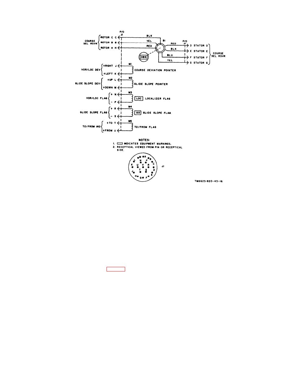
Figure 1-3. Indicator, Course ID-1347/ARN-82 or ID-1347A/ARN-82, schematic diagram.
and out to the radio receiver through pins F
t e s t set produces these signals either by
and D of connector P2. In Test Set, Radio
energizing the OBS resolver or by energiz-
TS-2500A/ARM-92,
ing the precision bearing transformers.
terminals
8 and 9
( s t a t o r s E and G) of transformer T2 are
a. BRG-OBS switch S2 determines which
common and connect to E of P6 and E of P2.
resolver circuit is used. When switch S2 is
In Test Set, Radio TS-2500A/ARM-92, sta-
i n the OBS position, the OBS resolver is
tors E and G connect to P2, pins E and G,
u s e d to produce the desired course.
The
through switches S3, S5, and S2.
OBS indicator is the same type as used in an
aircraft installation.
The 400-Hz reference
signal is applied to the rotor of the resolver
1-4.1. Resolver Transmitter Circuit
in the OBS indicator.
W h e n the rotor is
(Contained in Test Set, Radio TS-
t u r n e d , the voltage of the signal at stator
output is varied. A compass card is attached
2500A/ARM-92 only, fig. 4-9.1. )
to the rotor, providing an indication of the
Radio
course selected.
T h e voltage is routed to
Receiver
R - 1 3 8 8 A / A R N - 8 2 re-
quires 4 0 0 - H z resolver signals to derive
the radio receiver.
For more information
The
course deviation and to-from outputs.
on the OBS indicator, refer to TM 11-5826-
C h a n g e 2 1-4.1

