TM 11-6625-820-45
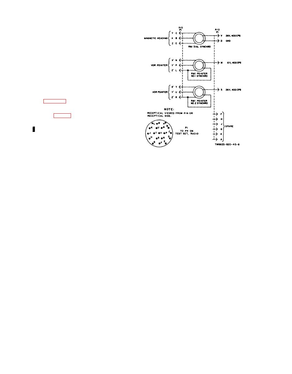
heading signal originates in the compass simu-
lator, and is routed to the RMI card. The RMI
needles give an indication of the direction of
a very high-frequency omnirange (vor) station.
In the test set, two needles are electrically
jumpered together. This makes the two nee-
dles track together. The vor signals are routed
from the radio receiver to the needle connec-
tions on P4. If the RMI card rotates to indi-
cate a magnetic heading, the needles will fol-
low the card rotation to keep in the direction
of the vor station. For more information on the
RMI refer to TM 115826-211-50 for Indica-
tor, Course ID250A/ARN. The RMI is shown
in figure 14.
1-8. Aid Box
The aid box is primarily intended for testing
a new AN/ARN-82 or AN/ARN-82A installa-
tion wiring harness, but it can be used for a
quick check on the test set. The main cir-
cuits are as follows:
vided to indicated when a circuit is made com-
Figure 1-4. Indicator, Course ID-250A/ARN,
p l e t e or when it is energized. Frequency
schematic diagram.
control information is given in a code by the
R2 is the current-limiting resistor for the FLAG
lamps. The lamps that check the power circuits
meter, and resistor R1 is a 1,000-ohm load for
glow when a current flows through them, in-
the FLAG meter.
dicating an energized circuit.
c. Audio Circuit. Resistor R7 drops the 26
volts, 400 cps to the voltage level desired,
applied to pin G of J1 and is routed to Zener
and this 400-cycle tone is fed to pin L of J2.
diode CR1. Resistor R8 and Zener diode CR1
form the 10-volt dc power supply for the meter
d. Compass RMI circuit. The signal from
circuits. Resistor R6 is a current-limiting resis-
the compass simulator at pins C and D of J1
tor for the TO-FROM meter. Resistor R5 is a
is connected to the RMI needle circuit through
current-limiting resistor for the DEVIATION
pins H and K of J1. This makes needle num-
meter. Resistor R3 (a 51l-ohm load) and re-
ber 1 (needle number 2 is not used) of the RMI
sistor R4 (a 1,000-ohm load) are the loading
follow the rotation of the RMI card when the
resistors for the DEVIATION meter. Resistor
aid box is used to check the test set.
1 - 6 Change 2

