
TM 11-6625-828-45
MP120, into tube assembly A106. Tighten tub MP123.
other end of tube MP110 and wire to connector J103.
(7) Replace mica washer MP117 and loop
(16) Replace and tighten plug MP109.
MP116. Solder loop MP116 to cable assemble W102.
(17) Seal plug MP1O9, screw H125, and
Insert plate MP115.
setscrews H119 by covering the item and the immediate
(8) Replace and solder R191 to loop M] 116
adjoining area with gray enamel.
and sleeve MP119.
d. Replace the RF attenuator assembly as follows:
(9) Insert sleeve assembly A105 in attenuator
(1) Position the RF attenuator assembly in its
A107.
proper location on the back panel. Replace four washers
(10) Replace spring MP113, washers HI12:
H117, and secure the lower portion of the attenuator
and two screws 11122 on attenuator assemble A107.
assembly and 1 VOLT connector J105 (fig. 3--6) to the
Tighten the two screws.
front panel with four screws H116.
(11) If removed, replace locknut H128 an
(2) Install shaft MP112 with washers H120
adjustment screw H126 on tube assembly A106.
and H121 in attenuator assembly A102. Replace gear
(12) Replace screw H127, washer H124, rack
MP111. Use an Allen wrench to tighten two setscrews
gear MP114, and screw H125 on the attenuator
H11119.
assembly. Tighten screw H125.
(3) Thread the hexagonal nut on the threaded
(13) Solder tube MP110 and wire to connector
portion of the attenuator protruding through the front
J105, and replace J105 on attenuator assembly A107.
panel to secure the upper portion of the attenuator
(14) Replace two screws 11116 and washer
assembly to the panel. Tighten the hexagon nut.
H117 that secure the connector to the attenuate
(4) Insert ATTEN connector J104 throughout
assembly. Tighten the screws.
the front panel and replace the four washers and four
(15) Replace connector J103 on attenuator
screws on the front panel that secure
assembly A107, and secure in position wit four screws
H11116 and washers H117. Solder the
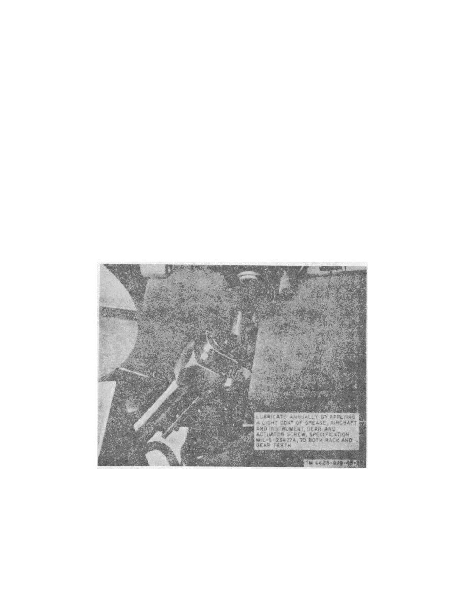
Figure 3-7. Lubrication of RF attenuator rack and spur gear assembly.
3-10
