TM 11-6625-828-45
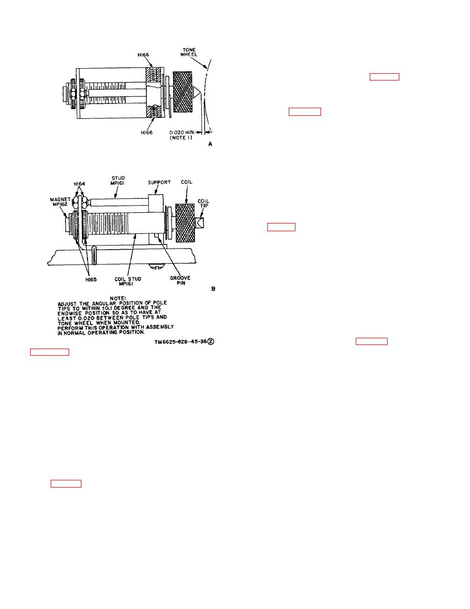
the set 3-14 on the side of the support facing the
direction in which the coil is to be moved.
(3) Connect the vacuum tube voltmeter test A,
leads to the terminals of coil L102 (fig. 3-8()) and adjust
the gap between the coil tip and the tone wheel until the
vacuum tube voltmeter indicates 14 volts -+0.01. Gap
adjustment is accomplished by backing off one knurled
nut H165 (fig. 3-8(1))and tightening the other nut.
Tighten the nut on the side of the bracket facing the
direction in which the tip is to be moved.
NOTE
The gap between the coil tip and the
tone wheel must always be greater
than 0.007 inch.
(4) Disconnect the vacuum tube voltmeter
and recheck the course error. If necessary, readjust the
angular position of coil L102 until the indicated error is
0.00.
(5) If coil L102 cannot be moved enough to
obtain a course error of 0.0 at 180 track also adjust coil
L101 (fig. 3-8()).
(6) If coil L101 was adjusted, coil L101 must
be set for a voltage of 14 volts i 0.01, and variable
resistor R138 (fig. 22) must be readjusted for a 0.00
course error (b(4) above).
d. 30 Track Alignment. Set the test set OMNI
TRACK switch to 30 and check the angular position and
voltage output of coil L104 (fig. 3-80) in the same
manner as specified for coil L102. Coil L104 voltage
must be 14 volts +0.01 and the course error, if any,
must be corrected to 0.0.
e. 1200 Track Alignment. Set the test set OMNI
TRACK switch to 120 and check the angular position and
voltage output of coil L105 (fig. 3-8()) in the same
manner as specified for coil L102. Coil L105 voltage
must be 14 volts _+0.01 and the course error, if any,
wheel generator.
must be corrected to 0.0.
(3) Remove the decade resistance box
f. 15 Track Alignment. Allow the test set to warm
replace with a fixed resistor (R139) having same
up for a minimum period of 2 hours, and then proceed as
approximate value as noted in (2) above
follows:
(4) Adjust variable resistor R138 until course
(1) Set the test set OMNI TRACK switch to
checker again indicates 0.00.
the 0 and set the course checker SELECTOR switch to
c. 180 Track Alignment. Set the test OMNI
0.
TRACK switch to 180 and proceed follows:
(2) Note the course error, if any, indicated on
(1) Set the course checker COURSE s, to
the course checker DIkGREES meter. Adjust variable
1800 and read the course error, if any, on course
resistor R188 (b(4) above), as necessary, to obtain a
checker DEGREES meter.
0.00 error.
(2) Adjust the angular position of coil 102 (fig.
(3) Set the test set OMNI TRACK switch to 15
3-80) until the course has 0.00 el Angular position
and the course checker SEL4ECTOR switch to 15.
adjustment is accomplished backing off one setscrew
H166 (fig. 3-8) tightening the other setscrew. Loosen
3-14

