
TM 11-6625-828-45
(variable resistor R131) until the %oM meter indicates at
db 0.1 above the 0.02 volt (6 db) and is as many db
the green line on the dial scale.
(within 0.1 db) above 0.02 volt as the 90-cycle output
(2) Use a small screwdriver to adjust the test
was below 0.02 volt.
e.j(10) Set the test set
set DEMOD control (variable resistor R224 until the
MODULATION switch to AMP LOC O) and set the filter
vacuum tube voltmeter indicates exactly 0.03 volt.
unit switch to 90 cycles. Check to see that the filter unit
(3) Set the test set MODULATION switch to
output is 2.0 db +0.1 above 0.02 volt (6 db).
90, and adjust 90- MOD control R130 t obtain a redline
(11) Set the filter unit switch to 150 cycles and
indication on the 7%M meter.
check to see that the filter unit output is 2.0 db +0.1
(4) Set the test set MODULATION switch to
below 0.02 volt (6 db) and is as many db (within 0.1 db)
150- and adjust 150- MOD control R144 t obtain a
below 0.02 volt as the 90-cycle output was above 0.02
redline indication on the % M meter.
volt.
(5) Set the test set MODULATION switch to
(12) Set the test set POWER-STANDBY switch
the AMP LOC + position and set the filter unit switch to
to STANDBY and disconnect and remove all test
90 cycles. Check to see that the vacuum tube voltmeter
equipment. Replace the test set cabinet.
indicates 0.019 to 0.2 volt.
(6) Set the filter unit switch to 150-cycl and
note that the vacuum tube voltmeter indicates 0.019 to
0.021 volt.
(7) Set the filter unit switch to 90-cycl and
adjust the test set DEMOD control unit the vacuum tube
voltmeter indicates exactly 0.0 volt. Place the test set
MODULATION switch in the AMP LOC (O position.
(8) Check to see that the filter unit output is
2.0 db + 0.1 below the 0.02 volt (6 db).
(9) Set the filter unit switch to 150 cycle and
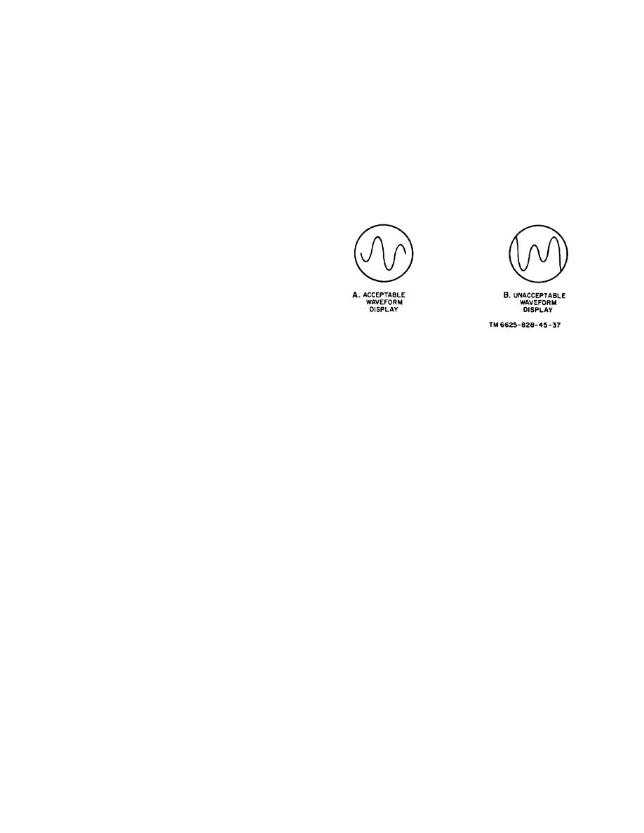
Figure 3-9. Phase adjustment oscilloscope display.
check to see that the filter unit output is 2.
3-16
