T.O. 33A1-3-358-11/TM 11-6625-842-15
Section VI
Paragraphs 6-1 to 6-14
NAVAIR 16-30APM239-2
SECTION VI
DEPOT OVERHAUL STANDARDS
6-1.
INTRODUCTION
6-2.
Transponder Test Set AN/APM-239A must be tested thoroughly after rebuild or repair to insure that
it meets adequate performance standards for return to stock and re-issue. Use the tests described in this
section to measure the performance of the repaired test set. It is mandatory that repaired equipment to be
re-issued, or returned to stock for re-issue, meet all of the performance standards given in this section.
6-3.
APPLICABLE REFERENCES.
6-4.
REPAIR STANDARDS. Applicable procedures of the Signal Corps depot performing this test and its
general standards for repaired signal equipment form a part of the requirements for testing this test set.
6-5.
TECHNICAL PUBLICATIONS. No technical publications are required other than this manual.
MODIFICATION WORK ORDERS. Perform all modification work orders applicable to this equipment
6-6.
before making the tests specified. DA Pam 310-7 lists all available MWO's.
6-7.
TEST FACILITIES REQUIRED.
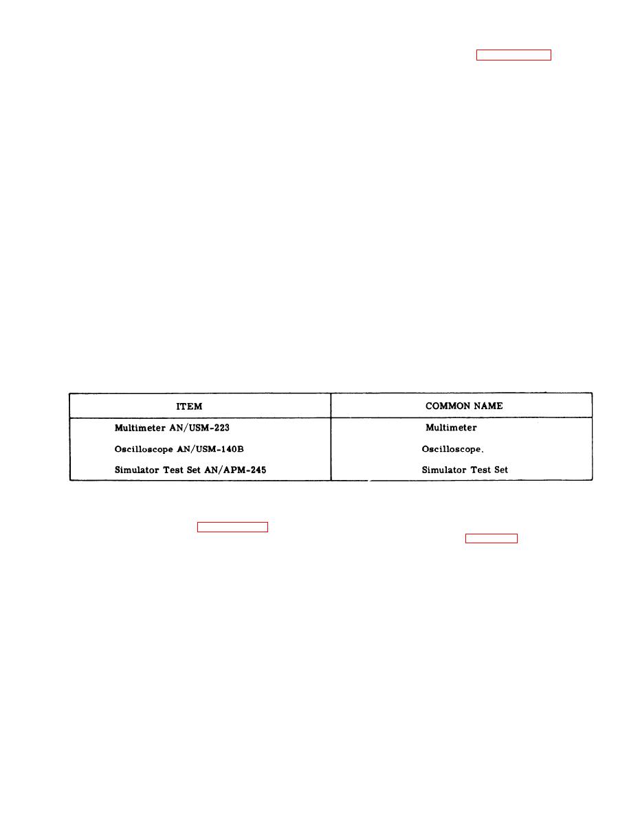
The following items are required for depot testing:
6-8.
6-9.
GENERAL TEST REQUIREMENTS.
6-10. A source of 115-volts a-c, 60-Hz, single phase and a source of 115-volts a-c, 400-Hz, single phase;
the test equipment listed in paragraph 6-8; and a locally fabricated test fixture are required to test a repaired
Test Set, Transponder Set AN/APM-239A. The test fixture, shown schematically in figure 6-1, is used to
provide loads to the power supply portion of the test set.
6-11. Testing will be simplified if connections and panel-control settings are made initially and modifications
are made as required for the individual tests. Initially, set the controls to the positions indicated in figure
6-2. The tests are to be performed in the exact sequence presented. When starting a new test, leave all
controls in their last used positions of the previous test. Do not set controls to their initial positions unless
specifically directed to do so.
6-12. Remove jumper plug P5 from MODE C ENCODER connector J5 for all tests. Replace the jumper plug
at the conclusion of the tests.
6 - 1 3 . TESTS.
6-14. MODE C SIMULATOR RESISTANCES TEST.
a.
Set the multimeter for use as an ohmmeter to measure approximately 110-kilohms, and connect the
multimeter common probe to MODE C ENCODER connector J5, terminal R (ground).
b. In turn, connect the multimeter test probe to MODE C ENCODER connector J5, terminals s, g, b,
L, f, J, P, T, F, m, and p. A reading between 99-kilohms and 121-kilohms is required at each terminal.
6-1


