T.O. 33A1-3-358-11/TM 11-6625-842-15
Section VI
NAVAIR 16-30APM239-2
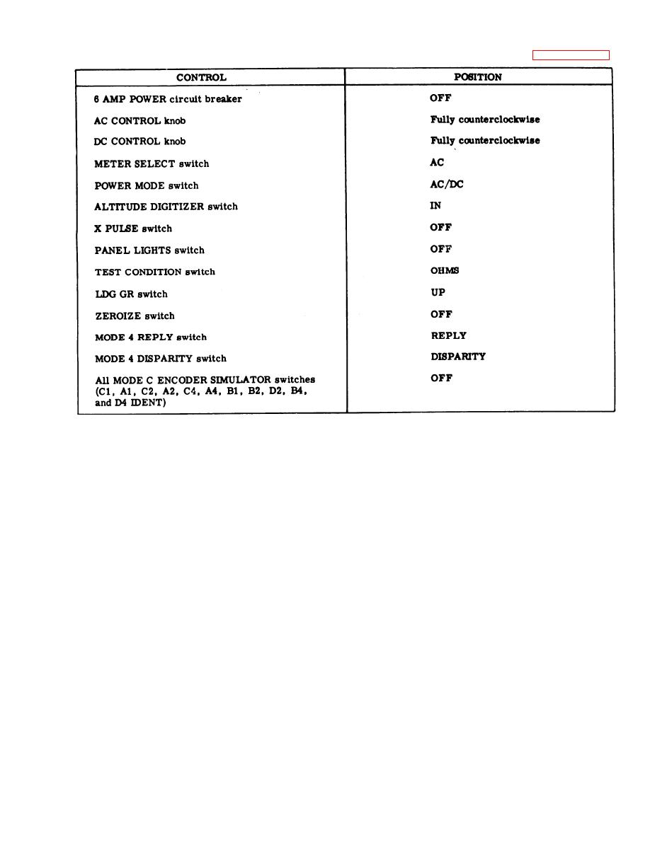
Figure 6-2. Initial Control Settings
Set all the MODE C ENCODER SIMULATOR switches (C1, A1, C2, A2, C4, A4, B1, B2, D2,
c.
B4, and D4 IDENT) to ON.
In turn, connect the multimeter test probe to MODE C ENCODER connector J5, terminals s, g,
d.
b, L, f, J, P, T, F, m, and p. A reading between 2700 ohms and 3300 ohms is required at each terminal
to ground.
Disconnect the multimeter from the test set.
e.
6-15. A-C POWER SUPPLY TESTS.
Connect the test fixture connector to TRANSPONDER connector J2.
a.
Connect power cable W3 between POWER INPUT connector J1 and a source of 115 volts, 400 Hz,
b.
single phase.
Set switches S1, S2, and S3 of the test fixture open. Set switch S4 of the test fixture closed.
c.
Set the multimeter to measure a-c voltage of approximately 115 volts. Connect the common
d.
probe of the multimeter to test fixture test point TP3, and connect the test probe of the multimeter to test
point TP2.
e.
Set the 6 AMP POWER circuit breaker to ON and check that the POWER ON indicator illuminates.
Adjust the AC CONTROL knob to obtain an indication of 115 volts on the test set voltmeter. The
f.
multimeter must indicate between 109 volts and 121 volts.
Disconnect the multimeter.
g.
h.
Rotate the AC CONTROL knob from fully counterclockwise to fully clockwise. The test set
voltmeter must indicate 0-volts at the fully counterclockwise position, and must increase to a minimum value
of 125 volts as the knob is rotated clockwise to its fully clockwise position.
6-3


