TM 11-6625-2709-40
Section Il. DETAILED CIRCUIT FUNCTIONING
The test set supplies all the necessary power con-
nections for the operation of a VOR radio receiver or a
glideslope or marker beacon receiver. The operation
of these power circuits is described below. Refer to
appropriate test set schematic as indicated while
reading paragraphs a, b, and c below.
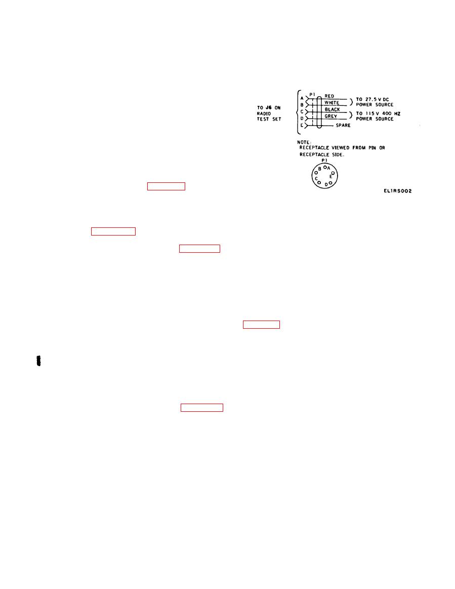
a. The external sources of power are connected to
J6 by Electrical Power Cable Assembly CX-
11568/ARM-92 (power cable) (figure 1-2). The 27.5
volts dc is applied bettween pins A and B, the positive
side to pin A, ground to pin B. The 115 volts, 400 Hz is
CX-11568/ARM-92, schematic diagram.
applied with the high side to pin D. The connection
from J6-A is made through fuse F2 to P5-Z on the
desired phase shift. The OBS indicator is the same
control unit (figure 4-12). When the control unit
type as used in an aircraft installation. The 30-Hz
power switch is in the PWR or TEST position, the
reference signal is applied to the rotor of the resolver
27.5-volt dc circuit is completed to P5-M (figure 4-11).
in the OBS indicator. When the rotor is turned, the
The 27.5 volts is then routed to relay K1. This voltage
phase of the signal at stator output is shifted. A com-
energizes relay K1, and the circuit is completed for
pass card is attached to the rotor, providing an in-
the 115 volts, 400 Hz from J6-D through fuse F1 to
dication of the number of degrees of phase shift. This
transformer T1. Transformer T1 steps down the 115
voltage is routed to the radio receiver. For more in-
volts, 400 Hz to 26 volts, 400 Hz. The 26 volts, 400 Hz
formation on the OBS indicator, refer to TM 11-5826-
is routed to RMI connector P4, compass simulator
226-34 for Radio Receiving Set AN/ARN-82B. A
connector P1, and connector P3 of the radio receiver.
schematic diagram of the OBS indicator is shown in
b. When the control unit is in the PWR or TEST
position, the 27.5 volts dc is routed from P5-M to con-
nector P2 of the radio receiver. It is also routed from
b. A r e s o l v e r h a s t h e s a m e e l e c t r i c a l
P5-T through fuse F3 to connector P7 of the glideslope
characteristics as a transformer. Therefore, a
o r marker beacon receiver.
transformer can be used to simulate a resolver. When
c. Tuning information from the control unit is
switch S5 is in the BRG position, precision bearing
routed to connectors P2 and P7. For further informa-
transformer T2 and its switching circuits are used to
tion on the control unit, refer to TM 11-5826-226-34
produce the desired phase shift. The 30-Hz reference
for Radio Receiving Set AN/ARN-82B. A schematic
signal from the radio receiver is applied through
diagram of the control unit is shown in figure 4-11.
switch S5 to the primary of transformer T2. This
primary winding and resistor R11 simulate the rotor
of a resolver. The phase shift through the secondary
winding of the transformer must be the same as the
In the test set, the two circuits that shift the phase
phase shift in the stator windings of the resolver. This
of the 30-Hz reference signal are the OBS resolver
phase shift through transformer T2 is adjusted to 83
and precision bearing transformer T2. Their opera-
degrees at a dial setting of 300 degrees by the loading
tion is described below. In Radio Test Set TS-
o n the tertiary winding. The design of the
2500B/ARM-92, MODE switch S3 disables precision
transformer is such that the phase shift it produces is
bearing transformer T3 and adjusts the circuit of
stable with variations in alternating current (ac) or
transformer T2 whenever the phase-shifting mode is
direct current through the primary winding. The
needed (switch position, 30 HZ).
combination of the precisely tapped secondary win-
a. BRG-OBS switch S5 determines which phase-
dings of transformer T2 and the switching arrange-
shifting circuit is used. When switch S5 is in the OBS
ment (S4) produces the various voltage ratios that
position, the OBS resolver is used to produce the
correspond to the stator output of a standard
Change 2 1 - 5


