TM 11-6625-2709-40
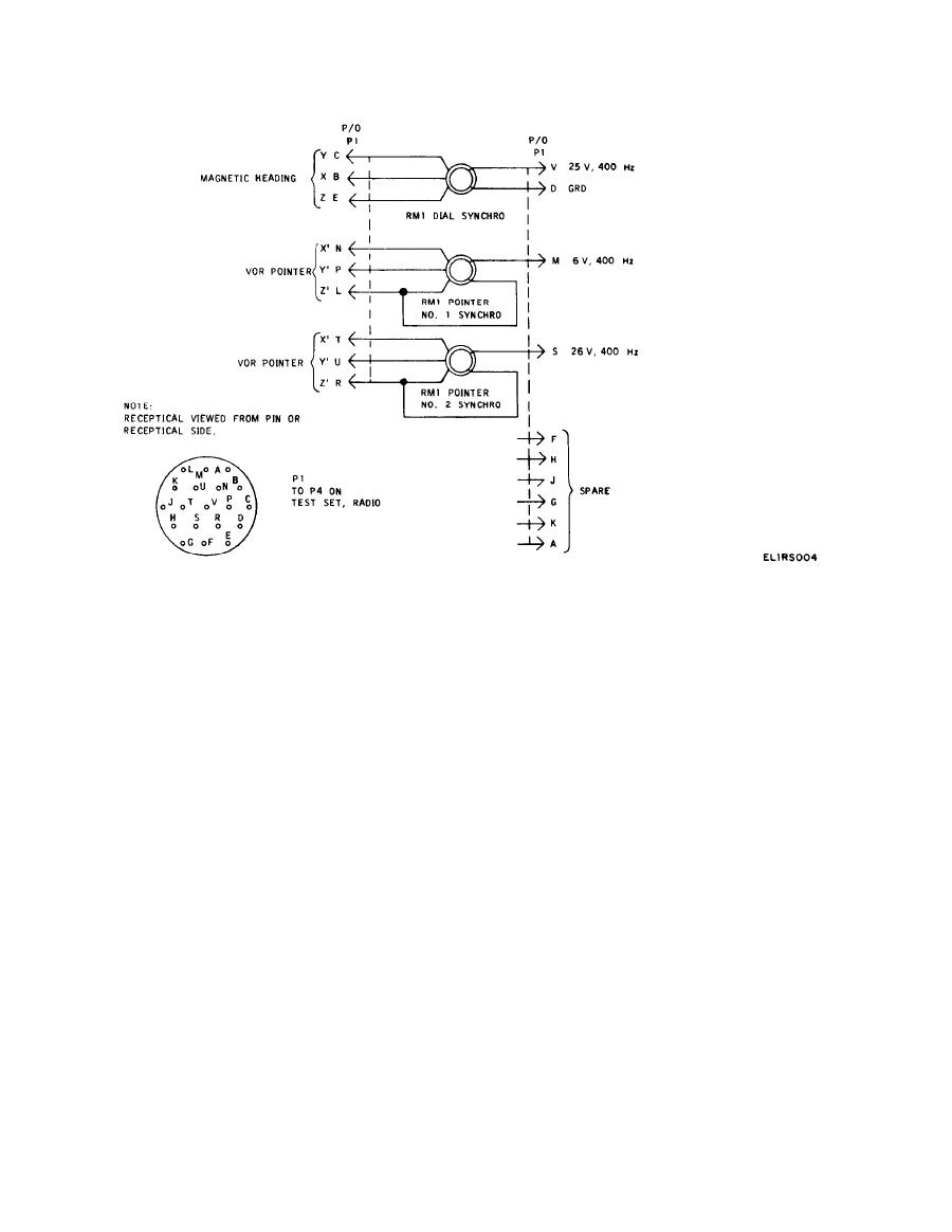
d. Compass RMI Circuit. The signal from the com-
limiting resistor for the FLAG meter, and resistor R1
pass simulator at J1-C and -D is connected to the RMI
is a 1000-ohm load for the FLAG meter.
needle circuit through J1-H and -K. This makes both
needle number 1 and needle number 2 of the RMI
c. Audio Circuit. Resistor R7 drops the 26 volts, 400
follow the rotation of the RMI card when the aid box
Hz to the voltage level desired, and this 400-Hz tone is
is used to check the test set.
fed to J2-L.


