
TM 11-6625-2709-40
test set produces these signals either by energizing
resolver. Each clockwise position of switch S4
the OBS resolver or by energizing the precision bear-
simulates a clockwise rotation of a resolver rotor in
ing transformers.
precise 30-degree increments. With switch S5 in the
BRG position, the output voltage path from
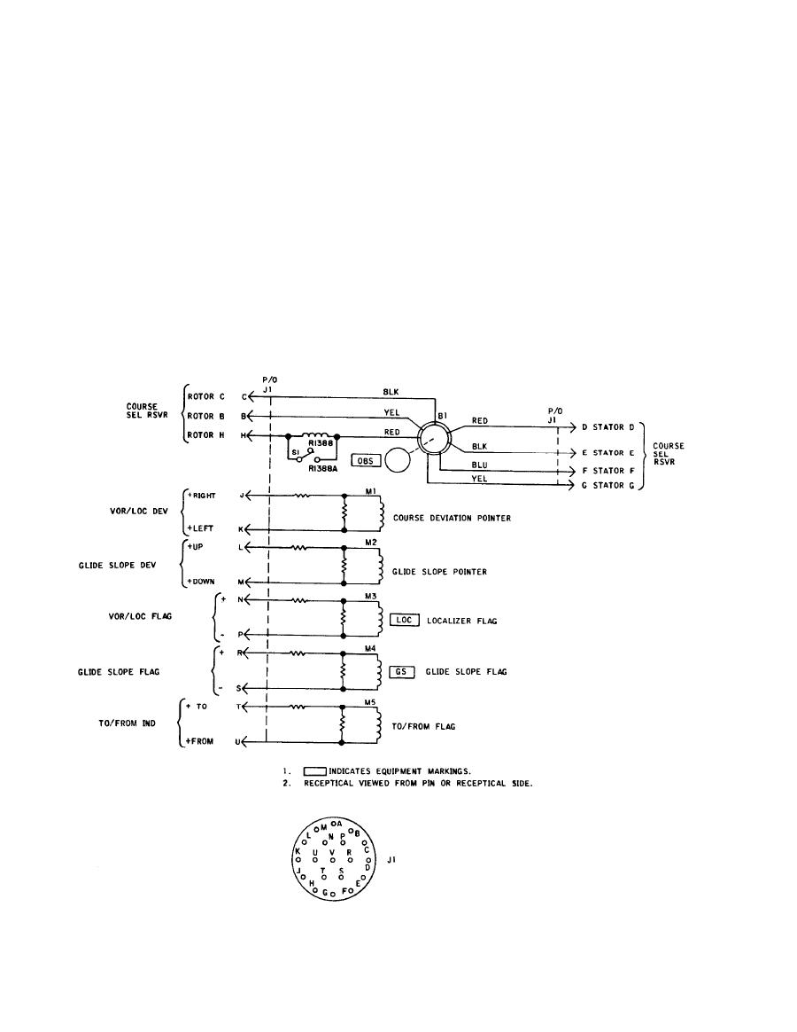
a. BRG-OBS switch S5 determines which resolver
transformer T2 is through switch S4, through switch
circuit is used. When switch S5 is in the OBS position,
S3 in Radio Test Set TS-2500B/ARM-92, through
the OBS resolver is used to produce the desired
switch S5, and out to the radio receiver through P2-F
course. The OBS indicator is the same type as used in
and -D. In Radio Test Set TS-2500B/ARM-92, stators
an aircraft installation. The 400-Hz reference signal
E and G connect to P2-E and -G through switches S3,
is applied to the rotor of the resolver in the OBS in-
S5, and S4.
dicator. When the rotor is turned, the voltage of the
signal at stator output is varied. A compass card is
1-7. Resolver Transmitter Circuit.
attached to the rotor, providing an indication of the
course selected. The voltage is routed to the radio
receiver. For more information on the OBS indicator,
The radio receiver requires 400-Hz resolver signals
refer to TM 11-5826-226-34 for Radio Receiving Set
to derive course deviation and to-from outputs. The
EL1RS003
