
TM 11-6625-2718-14&P
Item No.
Function
Control indicator, or connector
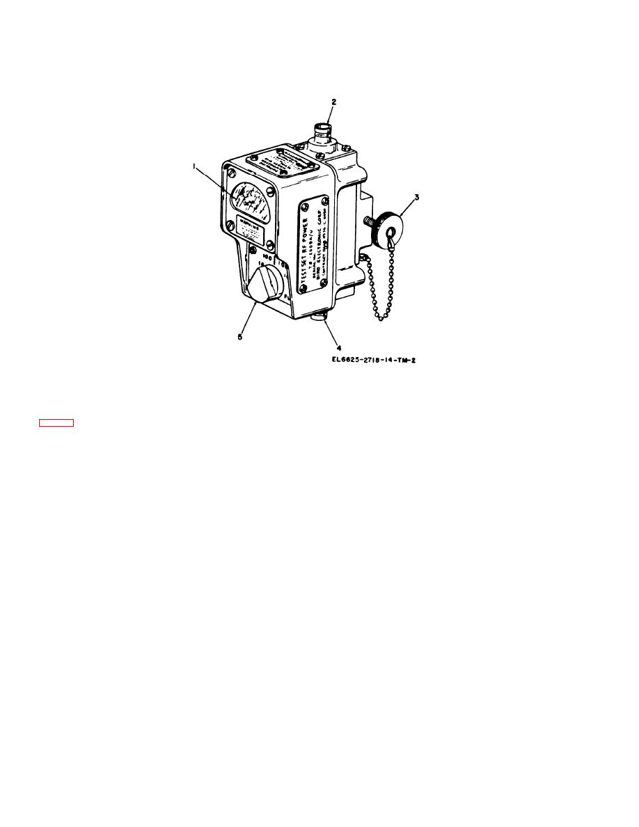
1
Meter
Indicates power measured by the test set. The dual scale
indications are 0 to 100 watts and 0 to 10 watts. The upper
scale corresponds to the 100 watt selector switch setting. The
lower scale corresponds to the 10 watt selector switch setting.
2
Transmitter connector (female BNC).
Provides a connection through which transmitter power is applied
to the test set. The connector mates with connectors supplied on
Cable Assembly CG-409G/U.
3
Provides a method of attaching and removing test set from
Clamping screw
mounting on related equipment.
4
Provides a connection through which transmitter output is applied
Antenna cable connector (female BNC).
to the antenna.
5
Determines the power level and direction indicated by the meter.
Selector switch
When the switch pointer is set to the left, toward RFL, the
meter will indicate reflected power. When the switch pointer is
set to the right, toward FWD, the meter will indicate forward
power. When the switch pointer is in the 100 position, the meter
will indicate in the 0 to 100-watt range. When the switch pointer
is moved to and held in the 10 position, the meter will indicate
in the 0 to 10 watt range. When released, the switch will
automatically return to the 0 to 100-watt range.
Section Ill. OPERATION UNDER USUAL CONDITIONS
Remove the TS-2609A/U and Cable Assembly,
Radio Frequency CG-409G/U from Case, Test
WARNING
Set CY-6785/U and install them as follows:
T h e transmitter must be deenergized
a. Reenergize the transmitter.
before connecting the TS-2609A/U to
transmitter output.
