TM 11-6625-2950-13
e. CONTROL switch S8 connects the uhf receiver-
electrical power between the interconnecting box and the
transmitter mode control circuit through interconnecting
uhf receiver-transmitter. The blower motor receives 115
box connector J2. The four positions supply either a logic
vac operating power directly from the interconnecting
high (open) or a logic low (ground) to the uhf receiver-
box. A 27.5 vdc primary power input, a 27.5 vdc primary
transmitter to change the operating mode. Refer to TM
power return, and a POWER ON/OFF control line are
11-5841-286-13 for a functional description of the logic
routed from the interconnecting box to the power supply
circuits controlling the uhf receiver-transmitter operating
of the uhf receiver-transmitter through the air cooler. J1
mode.
is a direct connection to the uhf receiver-transmitter.
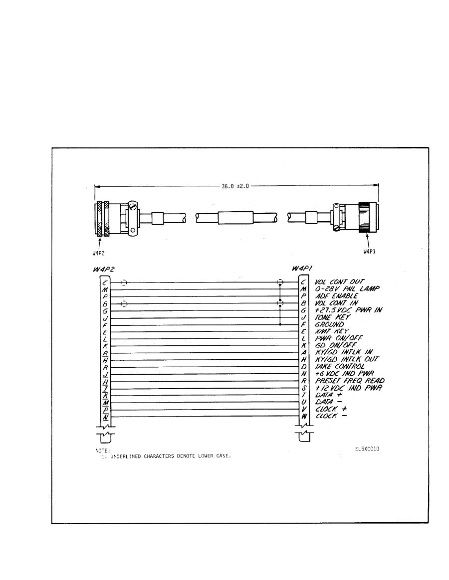
Cable assembly W2 connects the air cooler J2 to the
4 - 3 . Air Cooler
interconnecting box J1.
The air cooler provides cooling airflow to the uhf
receiver-transmitter. It also provides an interface for


