
TM 11-6625-2950-13
-) and dc operating power are provided to the indicator
through interconnecting box J3. The indicator is made
The headset adapter enables the operator to perform
up of four plug-together printed circuit assemblies.
a talk/listen test on the uhf receiver-transmitter. It is
Board 4 (A4) contains the serial data line receiver and
connected to the uhf receiver-transmitter J3 and provides:
one-half of the serial-to-parallel conversion circuitry.
Board 3 (A3) contains the other half of the serial-to-
Microphone H-157/AIC.
parallel circuitry and an error detector. Board 2 (A2)
b. Amplification of Headset-Microphone H-157/
contains the gating logic that selects the proper parallel
AIC output sufficient to modulate transmitter.
data for display (frequency data, channel number data,
c. Audio gain control of output of Headset-Micro-
or guard data). Board 1 (A1) contains the BCD (binary
phone H-157/AIC.
coded decimal)-to-decimal decoder/drivers for the mag-
netic wheel indicators and a transistor switch to remove
4-5. Indicator
full operating voltage from the wheels during steady state
The indicator logic circuits and indicators provide a
conditions.
6-digit readout of the manually selected channel fre-
quency, a 2-digit readout of the selected preset channel
number, or a single digit (G) guard channel indication.
The logic driven indicators are magnetically activated
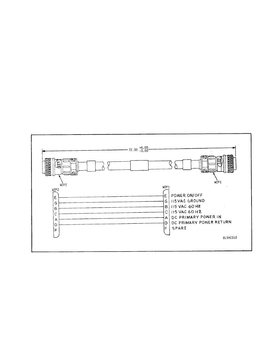
The five cable assemblies provide connections for the
equipment to be tested.
wheels. Input serial data (data+, data-, clock+, and clock
