
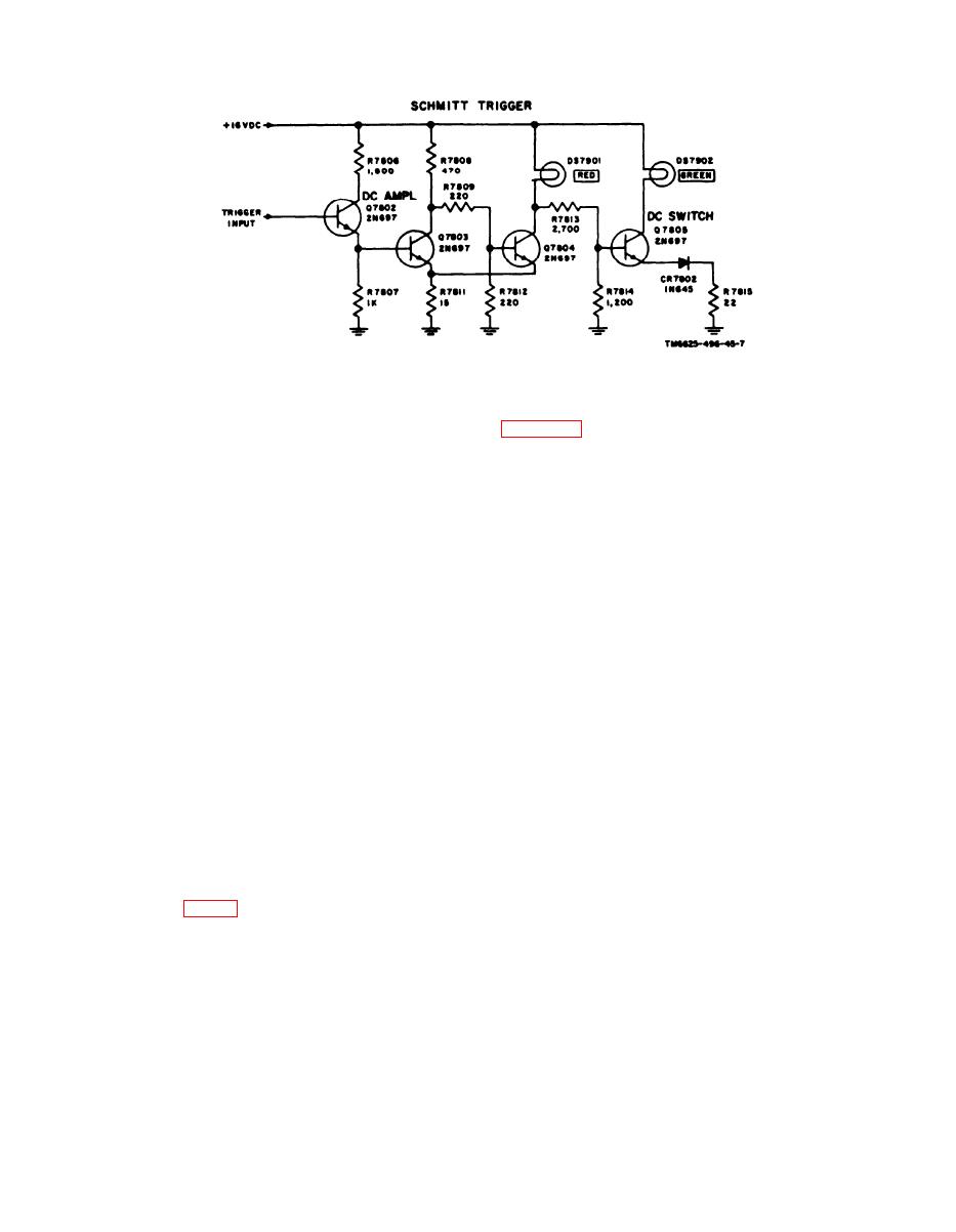
Figure 7. Schmitt trigger circuit, schematic diagram.
RT-246/VRC, or RT-524/VRC under test.
a. Resistor R7817 and rheostat R7816
form a voltage divider. Rheostat R7816 is
tion diagram of a typical test setup for an
adjusted SO that the minimum source volt-
RT-246/VRC or RT-524/VRC. The setup
age will cause the line voltage sensing
for testing an R-442/VRC is similar ex-
circuit to function. Transistor Q7806 is a
cept that an MT-1898/VRC is used instead
unijunction transistor. When the p o w e r
of an MT-1029/VRC .
source voltage is below minimum, the +16
a. The negative terminal of the vehicular
volts dc applied at base B2 of Q7806 biases
electrical system is connected to ground in
it to cutoff. If the power source voltage
the MT-1029/VRC through terminal A of
reaches or exceeds the minimum, the
J21. The positive terminal is connected
voltage applied at the emitter of Q7806
to terminal B of connector J21 on the MT-
overcomes the +16-volt bias and there will
1029/VRC; through fuse Fll to terminal
be conduction through base B2 and load
B of connector J24. The positive voltage
resistor R7818 to ground.
is connected by the CX-7899/VRM-l to
b. At the instant Q7806 conducts, a sharp
terminals B, C, and J of connector P401
positive-going pulse is generated at B1.
on the RT-246/VRC or RT-524/VRC to
The pulse is coupled through capacitor
provide power and control voltage for the
C7802 to the gate of dc switch CR7803. DC
equipment under test. The positive voltage
switch CR7803 is cut off until a positive
is also connected by the CX-7899/VRM-l
pulse is applied to its gate. Since CR7803
to terminal B of POWER connector J7902
is in series with the +16-volt dc supply
on the TS-1777/VRM-l.
line, operation of the TS-1777/VRM-l is
b. When switch S7901 is ON, positive
not possible until Q7806 generates a pulse
voltage is applied through fuse F7901 and
large enough to operate the gate of CR7803.
diode CR7901. Fuse F7901 protects the
Resistor R7819 is the dc return resistor
TS-1777/VRM-l and associated equip-
for the gate circuit.
ment. Diode CR7901 prevents possible
damage to the TS-1777/VRM-l if power of
12. Power Distribution
improper polarity is accidentally applied
to connector J7902. The positive voltage
appearing at diode CR7901 is applied to
Test Set, Radio AN/VRNI-l is supplied
26.0 volts dc from a power source such as
v o l t a g e dropping resistor R7901 and
a vehicular electrical system. The CX-
breakdown diode CR7902, which form a
7899/VRM-1 connects the power from an
+16-volt dc regulator. The regulated +16
MT-1029/VRC or MT-1898/VRC to the
volts dc is applied to terminal C of con-
TS-1777/VRM-l and to the R-442/VRC,
nectors J7907 and P7801. The voltage at
10
