
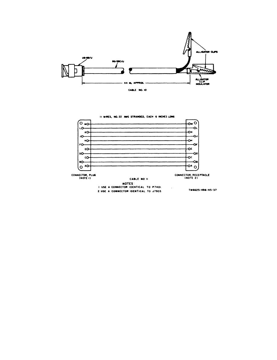
F i g u r e 21. Fabrication of special test cables.
26B/U; adjust potentiometer R7801
(3) Use the Transistor Power Supply
in the increasing voltage direction
721A and apply +5 volts dc to the
until a sharp drop in voltages indi-
test probe.
cates transistor Q7801 has trig-
(4) Measure the voltage at connector
gered. This should occur at
P7801-H with the ME-26B/U; ad-
approximately +9.5 volts dc.
just potentiometer R7803 for ap-
(8) Reduce the output of the 721A to
proximately +0.5 volt dc.
zero, then carefully increase it to
(5) Measure the voltage of the emitter
10.5 volts dc as indicated by the
of transistor Q7801 (ungrounded
TS-443/U.
side of potentiometer R7801) with
(9) Measure the dc voltage at connec-
the ME-26B/U; adjust potentiom-
tor P7801-H with the ME-26B/U;
eter R7801 for approximately +1
volt dc .
carefully a d just potentiometer
(6) Measure the 721A output with the
R7803 until a sudden drop in the
measured voltage i n d i c a t e s
TS443/U; increase the output to
13.0 volts dc.
GREEN indicator DS7902 has
switched on.
(7) Measure voltage at the emitter of
transistor Q7801 with the ME-
(10) Reduce the output of the 721A to
34
