
Section IV. FINAL ADJUSTMENTS
(3) Connect the TS-443/U across the
41. General
output terminals of the PP-2309/
Final adjustment of the TS-1777/VRM-l
u.
must be performed after major repair,
(4) Set the PP-2309/U for O-volt dc
parts replacement, or extensive alignment
output, and turn it on.
of individual plug-in assemblies. The final
(5) Set the TS-1777/VRM-l ON-OFF
adjustment procedures can also be used
switch to ON.
as a quick check to see if the TS-177/
Caution: Always remove the test
VRM-1 circuits are properly adjusted.
signal to the test probe before re-
moving power from the TS-177/
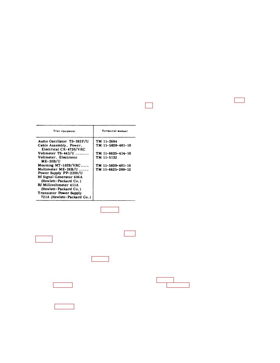
42. Test Equipment and Special. Tools
VRM-1.
Required
a. The following chart lists test equip-
ment required for final adjustment of Test
(1) Increase the PP-2309/U output for
an indication on the TS443/U of
Set, Radio AN/VRM-l. Associated techni-
cal manuals are also listed.
approximately 5 volts dc.
(2) Measure the dc voltage at the emit-
ter of transistor Q7806 (ungrounded
side of potentiometer R7816); use
the ME-26B/U. Adjust potentiom-
eter R7816 for an indication of less
than +2 volts dc.
(3) Increase- the output of the PP-
2309/U for an indication on the
TS-443/U of 21.5 volts dc.
(4) Adjust potentiometer R7816 in the
increasing voltage direction until
RED indicator lamp DS7901
switches on (as indicated by a sud-
den drop in voltage at the emitter
of Q7806). This action should occur
b. The special tool required for final
at approximately +12 volts dc.
adjustment is Cable No. 10 (fig. 21).
(5) Reduce the output of the PP-2309/
U to O volt dc; then increase it
43. Final Adjustments
slowly until RED indicator DS7901
lights. (Note a sudden drop in volt-
Adjust the AN/VRM-l as directed in the
age measured at the emitter of
procedures below, in the order given. Fig-
Q7806.) The PP-2309/U output
voltage as indicated on the TS-
adjust ments.
443/U, required to light RED indi-
Note: All voltages are measured to chassis un-
cator lamp DS7901, should be 21.5
leSS otherwise specified.
volts dc. Readjust the potentiom-
the following procedure prior to final ad-
eter R7816 as necessary to assure
this condition.
justments:
(1) Remove the TS-1777/VRM-l front
c. Voltage Supply Limits Sensing Cir-
panel and chassis from the case
shown in figure 24.
(1) Turn the TS-1777/VRM-l selector
(2) Connect the PP-2309/U, CX-4720/
switch to position 8.
VRC, MT-1029/VRC, CX-7899/
VRM-1, a n d TS-1777/VRM-l
(2) Increase the output of the PP-
2309/U to 26 volts dc.
33
