TM 11-6625-820-12
d. OBS indicator.
Function
Control or indicator
Provides manual control of the
OBS control_ _ _ _ _ _
direction of the bearing signal
from the OBS indicator.
Indicates the direction of the bear-
Course card_ _ _ _ _ _ _
ing signal from the OBS indicator.
To/from indicator_ _ _
Not used.
Not used.
Vor/localizer needle_ _ _
Not used.
Vor/localizer warn-
ing flag.
Not used.
Glide slope needle_ _ _ _
Not used.
Glide slope flag_ _ _ _
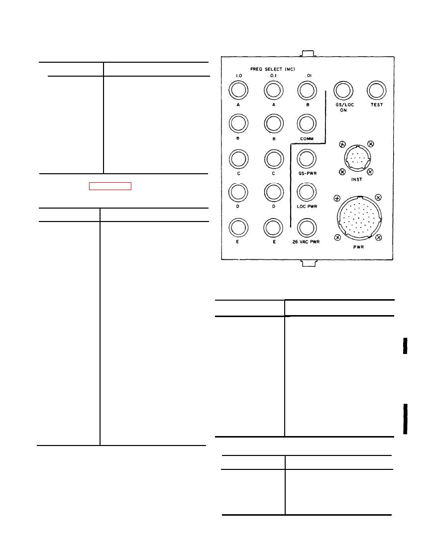
front panel indicators and controls.
Function
Indicator or connector
Provide indications to check the
FREQ SELECT
frequency control information
(MC) (12 lamps).
from the control unit.
When illuminated, it indicates the
26 VAC PWR lamp_
presence of the 26 volts, 400 cps
that is used by the receiver.
TM6625-820-12-2
When illuminated, it indicates the
LOC PWR lamp_ _ _ _
presence of the 27.5 volts dc
2-3.
Aid
box
indicators
and
connectors.
that is used by the receiver.
(1) Test set.
When illuminated, it indicates the
GS-PWR_ _ _ _ _
presence of the 27.5 volts dc
Position
Control
that is used by the glide slope
receiver.
N
(0
degrees).
COMPASS
SIMU-
Provides all power connections be-
PWR connector_ _ _ _
LATOR.
tween the aid box and the test
VOR/LOC
if
testing
Radio
Re-
VOR/LOC
-
GLIDE
set, or the aircraft wiring.
ceiver
R-1388/ARN-82
or
SLOPE.
R-1388A/ARN-82.
GLIDE
Provides all instrument connections
INST connector_ _ _
SLOPE
if
testing
a
glide
between the aid box and the test
slope
receiver.
set, or the aircraft wiring.
Leave
in
released
position.
SERVO
AMP
TEST lamp_ _ _ _ _ _
When illuminated, it indicates the
TEST.
presence of a ground that is
Either
position.
BRG-OBS- - - - - - - - -
used to set the receiver in a
N
(0
degrees).
OBS
-------------------
self-test mode.
0.
BEARING- - - - - - - - - -
When illuminated, it indicates the
GS/LOC ON lamp_ _ _
A
for
AN/ARN-82;
B
for
RECEIVER
presence of a ground that is
AN/ARN-82A
MODEL
used to turn on a glide slope re-
(TS-2500A/
ceiver by completing its primary
ARM-92A
only).
power circuit.
(2) Control unit.
Position
Control
2-4. Preliminary Starting Procedures
OFF.
Power switch_ _ _ _ _ _ _
Set
to
desired
Megacycle selector_ _ _
a. Control Settings. Set the controls on the test
Set
to
desired
Kilocycle selector_ _ _
set and the control unit to the positions listed in
Maximum
counterclockwise.
VOL_ _ _ _ _ _ _ _ _
the following charts.
3 2-5
Change

