T.O. 33A1-3-358-11/TM 11-6625-842-15
Section III
NAVAIR 16-30APM239-2
Paragraphs 3-5 to 3-14
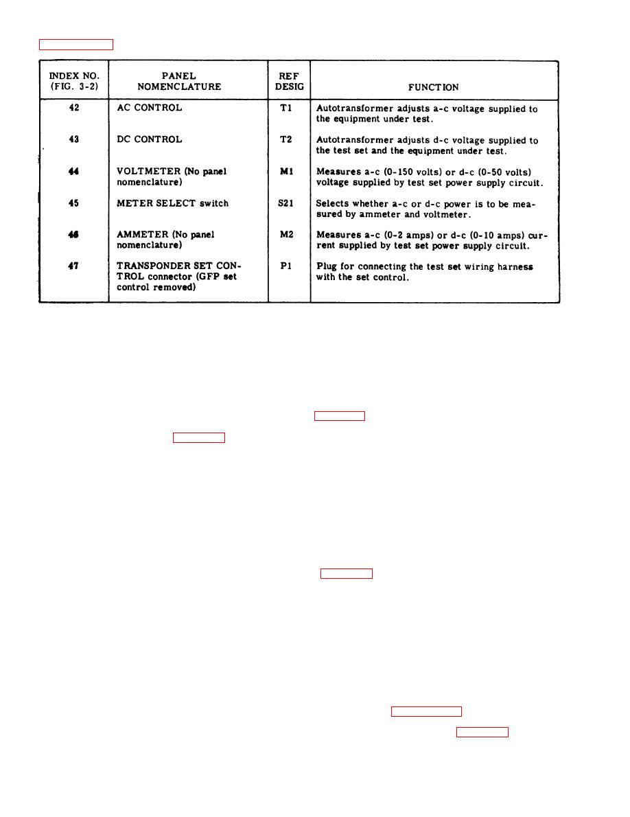
Figure 3-1. Controls, Indicators, and Connectors (Sheet 4 of 4)
MULTIMETER ME-358/APM-239A.
3-5.
Multimeter ME-358/APM-239A (fault isolation meter) is used in conjunction with cable W9 to select and
3-6.
measure significant receiver-transmitter voltages and the crystal mixer current when connected to the test
module of the receiver-transmitter of Transponder Set AN/APX-64 only. In addition, any of four video signals
available in the test module may be selected for monitoring at the fault isolation meter BNC connector. The
schematic diagram of the fault isolation meter is shown in figure 4-5. A chart showing the meter readings to
be expected for each position of the fault isolation meter selector switch when the receiver-transmitter is oper-
ating properly is provided in figure 3-3.
IF AMPLIFIER EXTENSION ASSEMBLY.
3-7.
The IF amplifier extender frame assembly consists of an aluminum frame and an integral cable assem-
3-8.
bly. Plug P1 of the cable mates with the IF Amplifier Module jack on the receiver-transmitter chassis, and
plug P2 mates with plug P201 of IF Amplifier Module AM-4359/APX-64, while the frame provides mechanical
support to extend the module beyond the receiver-transmitter for ease of access in trouble shooting and testing.
COAXIAL ADAPTERS.
3-9.
3-10. Five coaxial adapters are provided to adapt the various series coaxial connectors found on receiver-
transmitters to standard Series BNC, to facilitate use with associated test equipment. A tabular listing of all
coaxial adapters, giving type and application, is provided in figure 3-4.
3-11. EXTENDER BOARDS.
3-12. Fifteen extender boards are provided to facilitate maintenance of the printed circuit boards of the
receiver-transmitter modules. These extender boards fulfill the same function for the printed circuit boards
as does the IF Amplifier Extender Frame for the IF Amplifier Module. Since the receiver-transmitter chassis
receptacles for the printed boards use key pins to prevent improper insertion of the receiver-transmitter mod-
ules, the properly keyed extender board must be used during trouble shooting and testing. Each of the extender
boards is marked to indicate the particular printed board with which it is to be used.
3-13. CABLES.
3-14. Various cables are provides to interconnect the components listed in paragraph 1-4 and to permit test
bench operation with certain modules removed from their mountings on the receiver-transmitter APX-64 or
-72 chassis only. A tabular listing of the various cables and their function is provided in figure 3-5,
3-4


