T.O. 33A1-3-358-11/TM 11-6625-842-15
Section III
NAVAIR 16-30APM239-2
Paragraphs 3-19 to 3-23
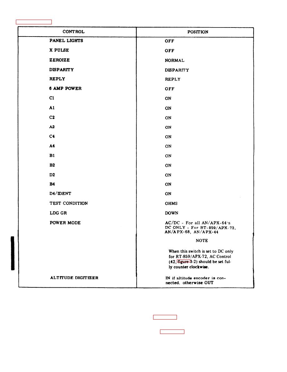
Figure 3-6. Preliminary Control Settings
3-19. INTERCONNECTION INFORMATION.
3-20. The interconnection diagram for the test set is shown in figure 3-7.
3-21. Cables are provided for the purpose of interconnecting the test set to the equipments of the IFF trans-
ponder set. Select the proper cables to be used in accordance with figure 3-7.
3-22. Connect P1 of the appropriate cycle to TRANSPONDER connector J2 of the test set, and connect P2 to
the multipin connector on the receiver-transmitter.
3-8
Change 6


