
T.O. 33A1-3-358-11/TM 11-6625-842-15
Section III
NAVAIR 16-30APM239-2
Paragraphs 3-24 to 3-29
3-23. Connection and mounting provisions exist on the front panel of the test set for Transponder Set Control
C-6280(P)/APX or C-6280A(P)/APX (supplied and installed with the test set as GFP). If the C-6280(P)/APX or
C-6280A(P)/APX is out, reach through the cutout in the front panel and draw out the internal cable. Bring the
C-6280(P)/APX or C-6280A(P)/APX near enough to the front panel to connect P1 of the cable to J201 of Trans-
ponder Set Control C-6280(P)/APX or 6280A(P)/APX. Locate the transponder set control in the cutout on the
panel and secure the turnlock fasteners. For Receiver-Transmitter RT-494/APX-44 only, use cable W14 to
connect Transponder Set Control C-2714/APX-44 to plug P1. In this case, the C-2714/APX-44 is placed on the
bench.
3-24. Under normal conditions, the Mode C encoder simulator circuitry of the test set is used during testing
of receiver-transmitters of transponder sets. Check that jumper plug P5 is properly seated in J5, MODE C
ENCODER, before starting tests. Jumper plug P5 is not utilized when using the test set in conjunction with an
actual altitude encoder. In this case, cable W15 is used to connect Altitude Encoder TRU-73/A or CPU-66/A
to connector J5, or cable W16 is used to connect Altitude Encoder CPU-46/A to connector J5. Transponder
Test Set TS-1843/APX and Transponder Computer KIT-1A/TSEC are connected to connectors J3 and J4,
respectively.
3-25. USE OF EXTENDER CABLES AND ADAPTERS.
3-26. Paragraphs 3-5 through 3-14 describe the various accessory items. When using the extender cables or
coaxial adapters be sure that the proper mating terminations are used. Dc not force the connection or exert
bending or twisting stresses. Be sure that the connectors and adapters are fully seated.
3-27. USE OF EXTENDER BOARDS.
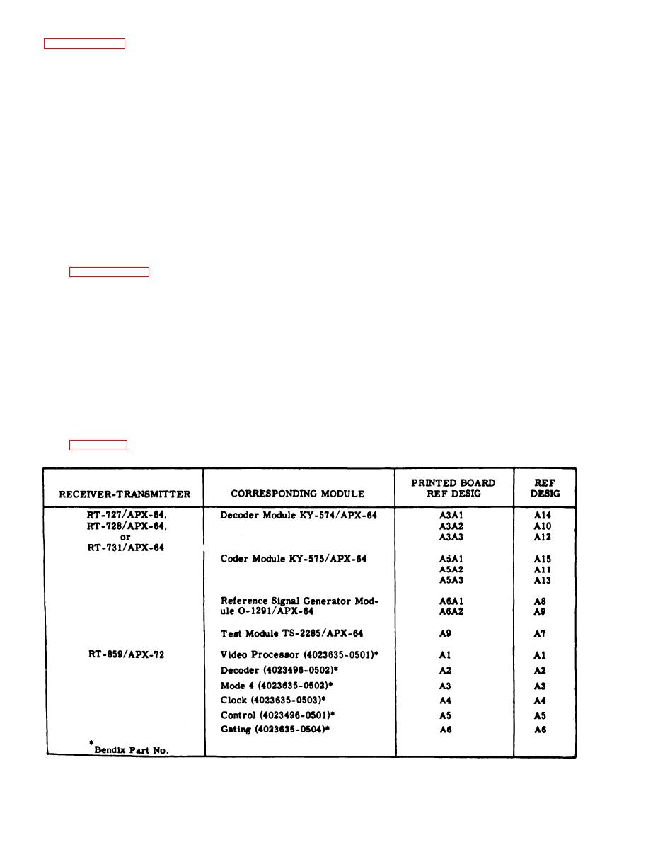
3-28. All of the extender boards contain markings which indicate the printed board assemblies with which they
may be used. The markings are explained as follows:
a.
Extender boards for use with the printed board assemblies of receiver-transmitters of AN/APX-64
include markings which are the same as the printed board to be extended, e.g., A3A1, A3A2, A3A3, A5A1,
A5A2, etc.
b.
Extender boards for use with Receiver-Transmitter RT-859/APX-72 have reference designations
which agree with the printed board assembly designations on the RT-859/APX-72.
3-29. Figure 3-8 is a tabular listing of the various receiver-transmitters, their corresponding modules, and
the proper extender board to be used with each printed board assembly.
Figure 3-8. Extender Board Data
3-10
Change 6
