
TM- 32-5811-025-14&P
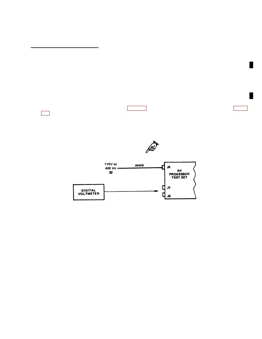
c. Power Supply Output Voltage Test. This test checks the proper operation of the RF processor test set power
supplies. To perform the test, proceed as follows:
(1) Disconnect W409 from J9.
(2) Connect connector J8 pins E and F together to enable ac interlock circuit.
(3) Connect lJ409 to J9.
(4) Push RF processor test set POWER ON pushbutton to on position (lamp lights).
(5) Monitor front-panel connector pins shown in table 6-5 for voltages shown using a digital voltmeter. Figure
Figure 6-4. Power Supply Output Voltage Test Setup
Change 1 6-11
