
TM 11-6625-2709-40
(3) Slip a 2-inch length of spaghetti over the
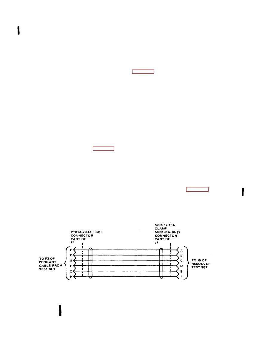
(7) Connector MS3106A-18-1S.
loose ends of the six wires.
(8) Connector MS3116A-18-32SW.
(4) Place clamp MS3057-10A over the end of the
spaghetti on the resolver test set cable.
(9) Binding posts (seven), Superior Electric
Company, DF 30RC.
(5) Connect the loose ends of the six wires to
the pins of the J1 female connectors as shown in
(10) Spaghetti, 3/4-inch diameter (5.5 feet
long).
(6) Tighten the clamps around the J1 connec-
(11) Small, enclosed metal box 3 x 4 x 5 inches.
tors on each cable.
Primary power requirements are 27.5 volts dc at 33
watts and 115 volts, 400 Hz at 92 watts. Temperature,
(1) Solder six 2-foot lengths of #22 AWG
humidity, and atmospheric pressure are not critical.
stranded insulated wire to pins C, D, E, F, G, and H
of male connector P1.
Details.
(2) Solder two 2-foot lengths of #22 AWG
stranded insulated wires to pins G and E of male con-
Fabricated cables are required to connect the test
nector P2.
set to Resolver Test Set AN/ASM-101 and Course In-
dicator Test Set AN/ASM-110. Refer to figures 4-1, 4-
2. and 4-3, and construct the cables as described
(3) Label the loose ends of the six wires with
the pin number to which each wire is connected.
below:
(4) Slip a 2-inch length of spaghetti over the
a. Resolver Test Set and Indicator Test Set Cables.
loose ends of the eight wires.
(1) Solder six 2-foot lengths of #22 AWG
(5) Mount and label seven binding posts on a
stranded, insulated wire to pins C, D, E, F, G, and H
small, enclosed metal box (figure 4-3).
of each male connector P1.
(6) Connect a 21.5-kilohm, 1%, 1/2-watt
(2) Label the loose ends of the six wires with
resistor from binding post J4 to binding post J5.
the pin number to which each wire is connected.
EL1RS020
Fabricated cable to resolver test set,
construction details.
Change 1
