put of the TS-421/U until the RED indicator
80A/U when the RED indicator goes out and the
lights.
GREEN indicator lights. This action must occur
between 6.00 and 7.80 volts. Decrease the output
e. Turn the selector switch to 6,
f. Carefully increase the output from the TS-
of the TS-42l/U until the RED indicator lights.
421/U and note the voltage indicated on the ME-
m. Turn the selector switch to 4.
30A/U when the RED indicator goes out and the
n. Carefully increase the output from the TS-
GREEN indicator lights. This action must occur
421/U and note the voltage indicated on the ME-
between 0.450 and 0.520 volt. Decrease the out-
30A/U when the RED indicator goes out and the
put of the TS421/U until the RED indicator
GREEN indicator lights. This action must occur
lights.
between 12.50 and 14.90 volts. Decrease the out-
g. Turn the selector switch to 6.
put of the TS-421/U to 0 volt.
h. Carefully increase the output from the TS-
o. Remove the ME-80A/U, the Special junction
421/U and note the voltage indicated on the ME-
box and the TS-421/U from the TS-1777/VRM-
30A/U when the RED indicator goes out and the
1 probe assembly.
GREEN indicator lights. This action must occur
47. Amplifier, 5.65-Mc, Tests
between 0.800 and 1.000 volt. Decrease the out-
(fig. 34.6)
put of the TS-421/U until the RED indicator
a. Connect the equipment as shown by the solid
lights.
i. rum the selector switch to 3.
lines in figure 34.6. Also make temporary connec-
j. Carefully increase the output from the TS-
tions A and B.
b. Using the special junction box, connect the
421/U and note the voltage indicated on the ME-
30A/U when the RED indicator goes out and the
AN/URM-145 across the TS-1777/VRM-l probe
tip and probe ground connector.
GREEN indicator lights. This action must occur
c. Turn the TS-1777/VRM-l selector switch
between 2.60 and 3.80 volts. Decrease the out-
to 12.
put of the TS-421/U until the RED indicator
lights.
d. Adjust the AN/GRM-50 for an output of
k. Turn the selector switch to 11.
5.65 mc 100 cps as indicated on the AN/USM-
26, and decrease the output to 0 volt, using the
l. Carefully increase the output from the TS-
fine attenuator.
421/U and note the voltage indicated on the ME-
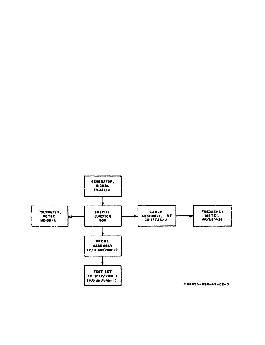
Figure 34.5. (Added) Audio voltage test setup, block diagram
7

