TM 11-6625-2632-14
CHAPTER 4
FUNCTIONING OF EQUIPMENT
4-1. Introduction
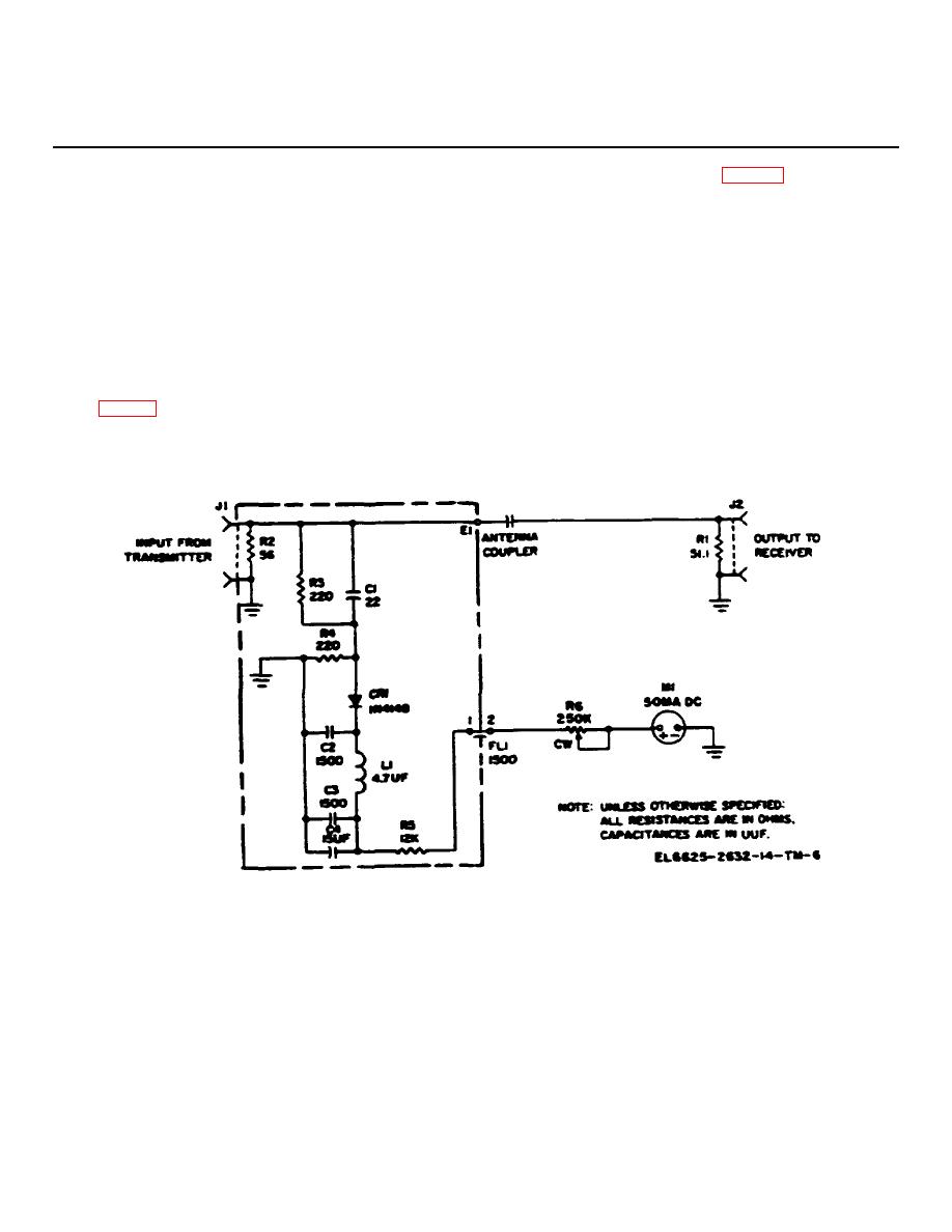
receiving radio set's antenna (fig. 4-1). The antenna
In use Radio Test Set AN/PRM-32 is connected between
coupler consists of two parts, one of which is a
two Radio Sets AN/PRC-90. One radio set transmits
feedthrough terminal which acts as an internal
and the other receives the transmitted signal through the
transmitting antenna. The signal from this terminal is
test set. The test set performs two functions. It
picked up approximately 2 inches away by an internal
attenuates the signal level from the transmitting radio set
receiving antenna, a wire connected to output connector
so that only a weak signal is applied to the antenna of
J2. Transmission of the signal across this air gap
provides the necessary attenuation.
the receiving radio set. This permits more sensitive
testing than would otherwise be possible.
It also
b. The signal from connector J1 is also passes
provides a meter indication of signal strength as visible
through a detector circuit, which is a half-way rectifying
evidence that a signal is being transmitted.
circuit, to potentiometer R6 and test set meter M1. Test
set meter M1 is a 50-microampere dc ammeter.
4-2. Theory of Operation
Potentiometer R6 adjusted during calibration so that test
set meter M1 registers in the green portion of its dial
a. The signal from the transmitting radio set is
marking when the signal passed through the antenna
received by the test set at connector J1 and passed
coupler is at an acceptable level.
through an antenna coupler to J2 as an output to the
Figure 4-1. Radio Test Set AN/PRM-32 schematic diagram.
4-1

