TM 11-6625-2632-14
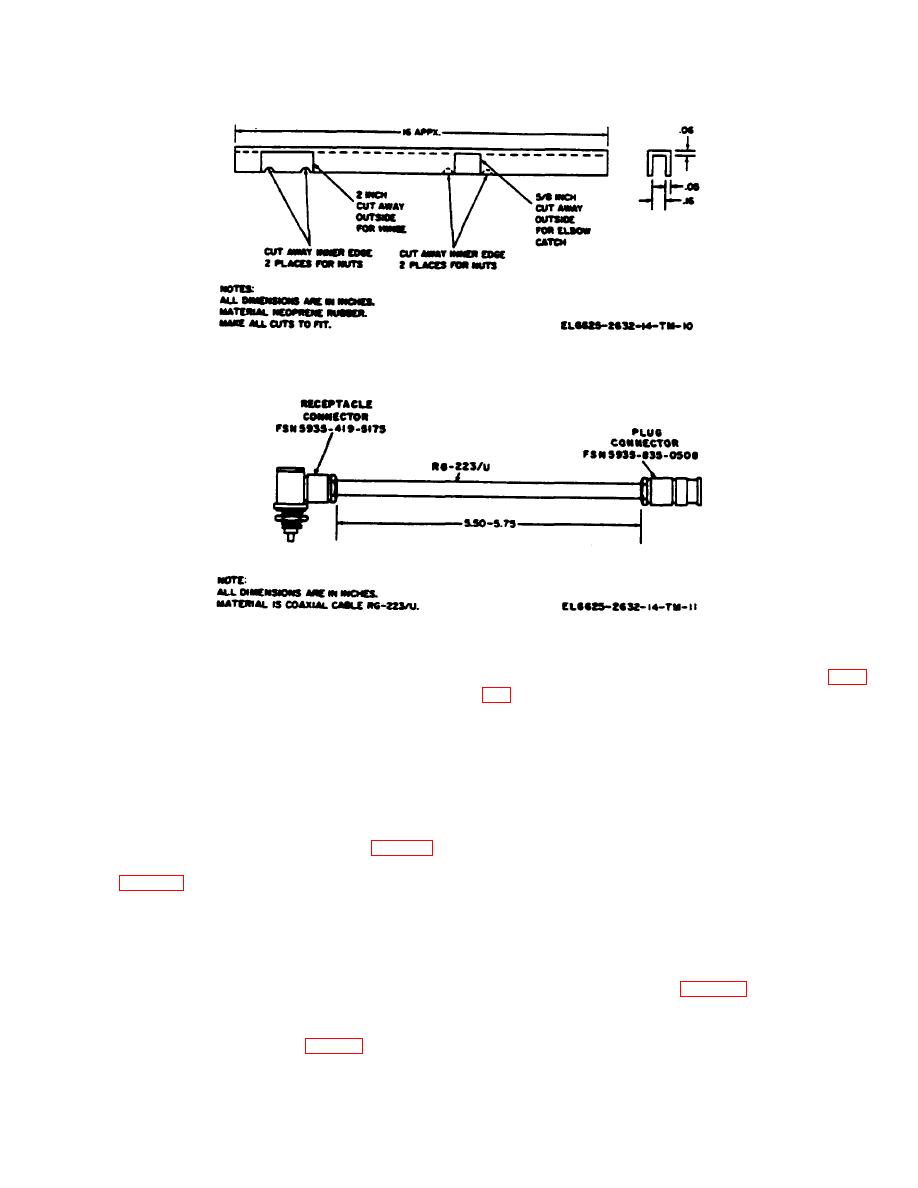
Figure 5-4. Neoprene gasket fabrication detail.
Figure 5-5. Cable assembly fabrication details.
c. Tag and unsolder three wires from connector J1
(1) Remove panel assembly from case (para
(4).
d. Unscrew hex nut (5) and remove terminal lug
(2) Tag wires Unscrew terminal nuts and
and resistor (6) and connector J1 (4).
remove wires from terminals of test set meter M1 (17).
(3) Unscrew mounting ring (16) from test set
filter capacitor FL1 (8).
meter M1, and lift test set meter M1 (17) out of top of
panel assembly.
f. Remove two screws (9) from panel (10) and lift
(4) Install replacement test set meter M1 in
detector housing assembly (3) off panel assembly.
panel assembly so that two nonrotating lugs (18) fit into
holes in panel (10).
5-10. Component Board Assembly Removal (fig. 5-3)
(5) Place mounting ring (16) over test set
a. Remove detector housing assembly from panel
meter M1 and tighten snugly (finger tight).
assembly (para 5-8).
(6) Untag wires, place them on terminals of
meter, and tighten terminal nuts.
(8).
b. Customary electronic repair procedures are
used for the replacement of all remaining components of
washers (13), and stepped spacers (14), and lift
Radio Test Set AN/PRM-32 after the component board
component board assembly (15) out of detector housing
assembly has been removed (para 5-9).
assembly (3).
5-11. Component Replacement
5-12. Repair Procedures
a. Physical Damage. Repair of physical dam-
5-6

