TM 11-6625-333-15
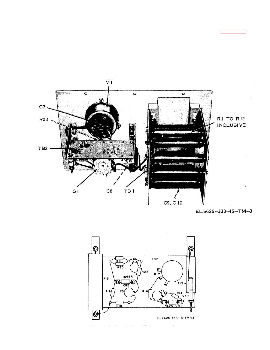
location information is given in figures 4-2 and
4-5. Replacement of Components
4-3.
The components of the ME-165/G can be readily
identified upon visual inspection. The front panel
of the meter on which all components are
The adjustment of the ME-165/G meter linearity
mounted, can be removed from the case by remov-
requires the test equipment and test setup
ing the 1 0 screws around the panel edge. Parts
Figure 4-3. Terminal board TB2, location of components.


