TM 11-6625-820-45
m. Lock potentiometer R1 shaft.
r. Set the test set BEARING switch to
n. If aligning Test Set, Radio TS-2500/
300 and the resolver bridge angle switch to
ARM-92, disconnect the equipment and re-
0 degree.
place the test set front panel. Omit steps o
through z.
o b t a i n a line of approximately 20 degrees
o. Disconnect the test set from the resol-
s l o p e from the horizontal (disregard any
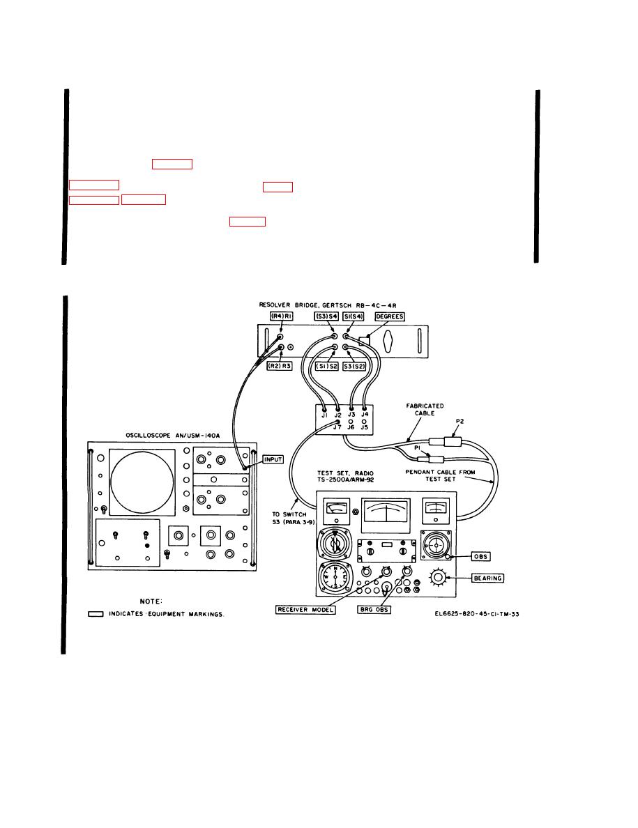
v e r test setup (fig. 2-9). Connect the test
ballooning).
s e t and the resolver bridge as shown in
t. With grease pencil or equivalent, draw
the slope line on the oscilloscope face; this
i s the maximum negative angle.
Draw a
p. Disconnect the wire to the wiper con-
l i n e of the same slope but the opposit e
nection of wafer H of switch S3 (fig. 3-3).
direction from the horizontal line; this is the
q. Connect jack J7 of the fabricated cable
maximum positive angle.
to the pin from which the wire was removed
u. Disconnect the jumper from J7 of the
in step p.
fabricated cable to the test set.
Figure 3-2. TS-2500A/ARM-92 precision BEARING alignment.
3-6 Change 2

