TM 11-6625-820-45
b. Tools. All tools required are contained
ASM-110.
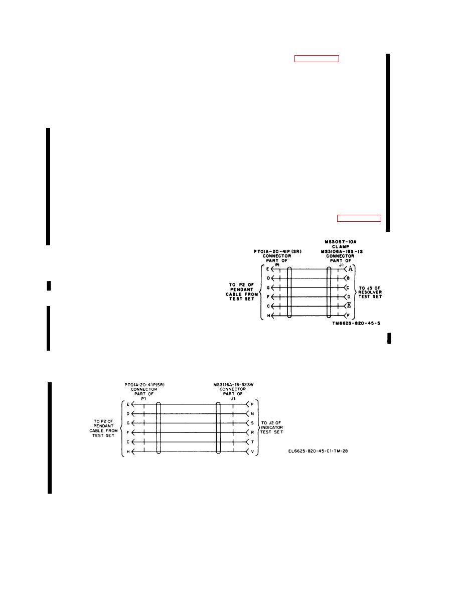
Refer to figures 4-1, 4-1.1, and
4-1.2 and construct the cables as described
in Tool Kit, Electronic Equipment TK105/G,
below.
Federal Stock No. 5180-610-8177.
a . Resolver Test Set and Indicator Test
c. Materials.
Set Cables.
(1) 1/4-inch barrel diameter.
(1) S o l d e r six 2-foot lengths of # 22
(2) T e l e p h o n e plug (1/4-inch diameter
A W G stranded, i n s u l a t e d wire to
barrel).
pins C, D, E, F, G, and H of each
(3) Wire, copper, i n s u l a t e d , stranded #
male connector P1.
22 AWG (40 feet long).
(2) Label the loose ends of the six wires
(4) Connectors ( 3 ) , Bendix PTOlA-20-
with the pin number to which each
40P(SR).
wire is connected.
PTO1A-12-10P
(5) Connector,
Bendix
(3) Slip a 2-inch length of spaghetti over
(SR).
the loose ends of the six wires.
(6) Clamp MS3057-10A.
(4) Place clamp MS3057-10A over the
(7) Connector MS3106A-18S-1S.
end of the spaghetti on the resolver
(8) Connector MS3116A-18-32SW.
test set cable.
(9) B i n d i n g posts (7) Superior Electric
(5) C o n n e c t the loose ends of the six
Company DF 30RC.
w i r e s to the pins of the J1 female
(10) Spaghetti, 3 / 4 - i n c h diameter (5.5
connectors as shown in figures 4-1
feet long).
and 4-1.1.
(11) Small enclosed metal box 3 x 4 x 5
inches.
4-3. Test Facilities
Primary power requirements are 27.5 volts
dc at 33 watts and 115 volts, 400 cps at 92
watts. Temperature, humidity, and atmos-
pheric pressure are not critical.
4-4. Fabricated Cable Construction
Details
Fabricated cables are required to connect
the test set to Test Set, Resolver AN/ASM-
Figure 4-1. Fabricated cable to resolver test set,
1 0 1 and Test Set, Indicator, Course AN/
construction details.
Figure 4-1.1. Fabricated cable to indicator test set, construction details.
4-2 Change 2

