TM 11-6625-820-45
v. Reconnect the wire d i s c o n n e c t e d in
step p.
w. Rotate the test set BEARING switch
and the resolver bridge angle switch simul-
t a n e o u s l y in 30-degree steps and note the
amount of error and the direction the line on
the oscilloscope slopes.
x. If the error exceeds the limit set in
r e f e r t o t h e t r a n s f o r m e r error
step t,
correction chart in paragraph 3-9.1.
y. Repeat steps c t h r o u g h y u n t i l a l l
error limits are met.
z. Disconnect the equipment and replace
the front panel.
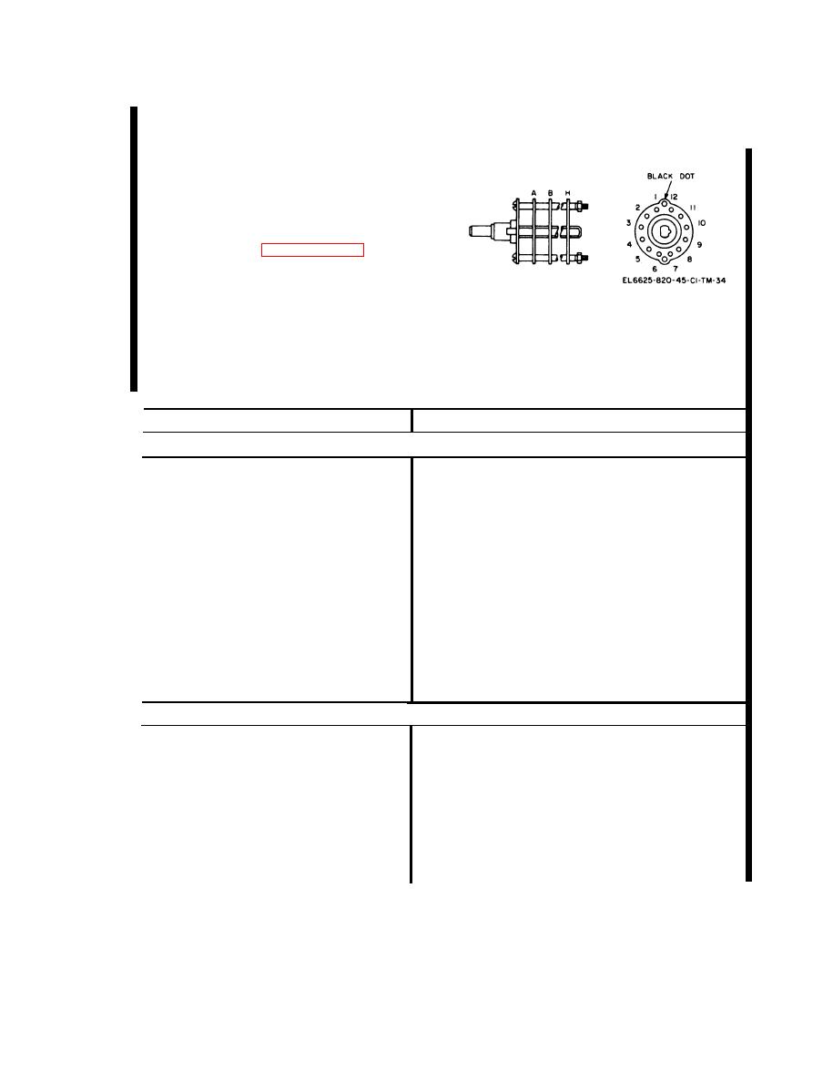
Figure 3-3. TS-2500A/ARM-92 switch S3
wafer and pin designation.
3-9.1. Transformer Error Correction
Chart
Symptom
Corrective
action
Positive error at 90 degrees
Positive error at 60 degrees g r e a t e r
Add resistance between terminals 9 and 10 of
than error at 90 degrees.
T2 to reduce error at 60 degrees; then add
resistance between terminals 10 and 11 of T2
to reduce error at 90 degrees.
Positive error at 60 degrees l e s s
Add resistance between terminals 10 and 11 of
than error at 90 degrees.
T2 to reduce error at 90 degrees; then add
resistance between terminals 9 and 10 of T2
to reduce error at 60 degrees.
No or small negative error at 60
Add resistance between terminals 10 and 11
degrees.
of T2 to reduce error at 90 degrees; then
add resistance between terminals 10 and 11 of
T1 to reduce error at 60 degrees.
Negative error at 60 degrees greater
Add resistance between terminals 10 and 11 of
than error at 90 degrees.
T1 to reduce error at 60 degrees; then add
resistance between terminals 10 and 11 of
T2 to reduce error at 90 degrees.
Negative error at 90 degrees
Negative error at 60 degrees greater
Add resistance between terminals 10 and 11 of
than error at 90 degrees.
T1 to reduce error at 60 degrees; then add
resistance between terminals 9 and 10 of T1
to reduce error at 90 degrees.
Negative error at 60 degrees less
Add resistance between terminals 9 and 10 of
than error at 90 degrees.
T1 to reduce error at 90 degrees; then add
resistance between terminals 10 and 11 of T1
to reduce error at 60 degrees.
Change 2
3-7

