TM 11-6625-820-45
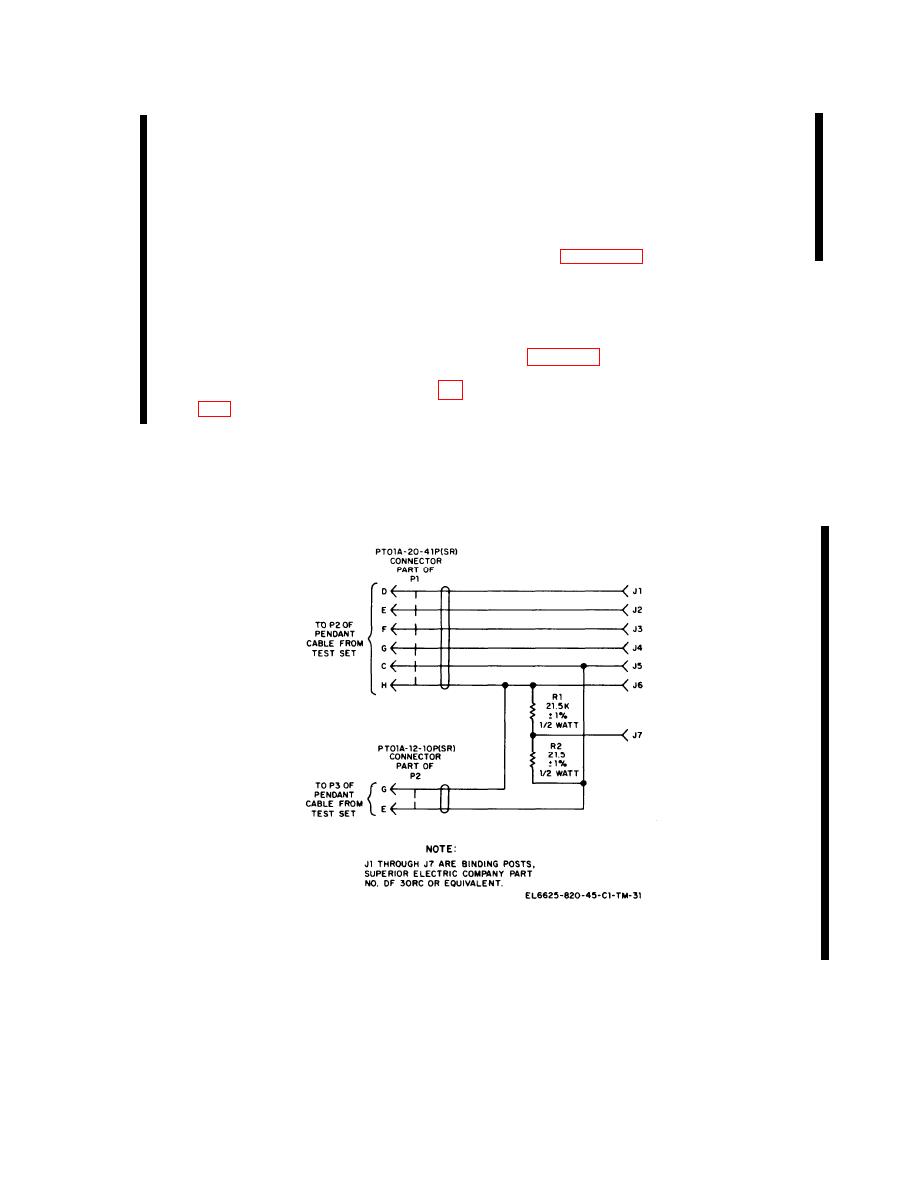
(6) C o n n e c t a 21.5-kilohm, 1%, 1/2-
(6) Tighten the clamps around the J1
watt resistor from binding post J6 to
connectors on each cable.
binding post J7.
b. Resolver Bridge Cable.
(7) Connect a 21.5-ohm, 1%, 1/2-watt
(1) S o l d e r six 2-foot lengths of # 22
resistor from binding post J5 to
AWG stranded insulated wire to pins
binding post J7.
C, D, E, F, G, and H of male con-
(8) Connect the loose ends of the eight
nector P1.
wires to the binding posts as shown
(2) S o l d e r two 2-foot lengths of # 22
AWG stranded insulated wire to
pins G and E of male connector P2.
(3) Label the loose ends of the six wires
4-5. Modification Work Orders
with the pin number to which each
wire is connected.
The performance standards listed in the
(4) S l i p a 2 - i n c h l e n g t h o f s p a g h e t t i
tests (paras 46 through 4-15) assume that the
over the loose end of the eight wires.
modification work orders, if any, have been
(5) Mount and label seven binding posts
performed. A listing of current modification
on a small enclosed metal box (fig.
work orders will be found in DA Pam 310-4.
Figure 4-1.2. Fabricated cable to resolver bridge, construction details.
Change 2 4-2.1

